9 Signet 8900 Multi-Parameter
8059-2
NC COM NO
RELAY A
NC COM NO
RELAY B
DC OUTPUT
+ -
DC INPUT
- +
+ S
3
L -
+
S
3
L -
INPUT
PASS-THRU
8059-4
NC COM NO
RELAY A
NC COM NO
RELAY B
NC COM NO
RELAY C
NC COM NO
RELAY D
DC OUTPUT
+ -
DC INPUT
- +
+ S
3
L -
+
S
3
L -
INPUT
PASS-THRU
COM
POWER
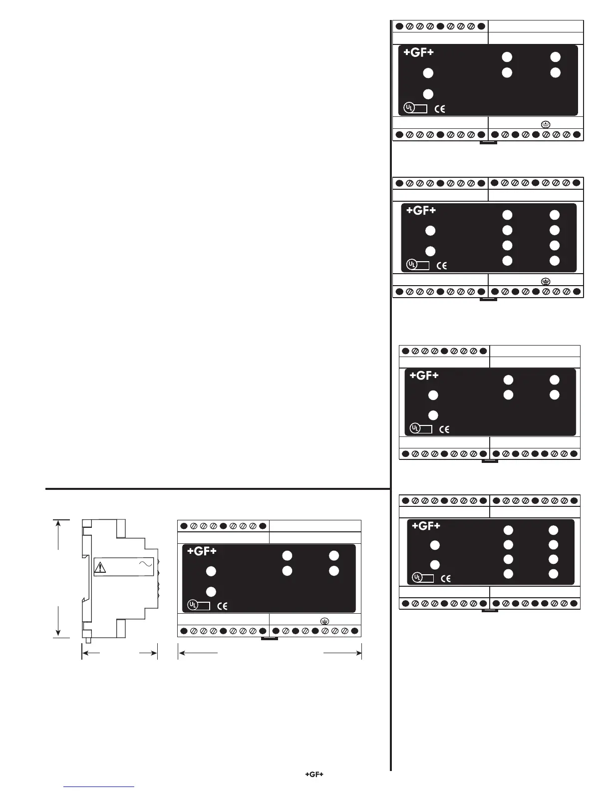
Signet 3-8059 Relay Module
Test A
Test B
Test C
Test D
Relay A
Relay B
Relay C
Relay D
LISTED
E171559
®
COM
POWER
Signet 3-8059 Relay Module
Test A
Test B
Relay A
Relay B
LISTED
E171559
®
4.5 8059 External Relay Module, optional; install zero (0) or one (1)
Mfr. Part No. Description
3-8059-2AC Two external dry-contact relays w/ power supply
3-8059-4AC Four external dry-contact relays w/ power supply
3-8059-2 Two external dry-contact relays
3-8059-4 Four external dry-contact relays
3-8050.396 RC Filter Kit
6205-0002 DIN Rail, 1m
6205-0003 End Clips, DIN Rail
• The 8900 will support up to eight (8) relays, though only four actually fi t directly
inside its compact
1
/
4
DIN enclosure. 8059 External Relay Modules of either two
or four relays may be connected to the 8900 via digital (S
3
L) at the I/O Module
(this does NOT consume a sensor input channel).
• External relays are completely independent of internal relays, so it is not
necessary for Relays 1 & 2 or 3 & 4 to be installed in order to use the external
relays. In the 8900 menus, external relays will always be identifi ed as Relays A,
B, C and D.
• 8059 versions with power supply are powered by universal AC line voltage
and may be used to power the 8900 with 24 VDC. Also, digital (S
3
L)
pass-thru
terminals on the 8059 can help to reduce sensor wiring congestion at the 8900.
See the 8059 instruction manual for details.
• External Relays mount on DIN rail inside a panel and can be tested remotely
from the 8900, or locally with switches built-in for convenience. They also
include LED relay status indicators, but the status of these and all relays is
available at all times in a single screen in the 8900 View mode.
• Any and all relays are freely assignable to any channel. Hysteresis and time
delay are adjustable for each relay.
• It is perfectly acceptable to mix and match relay types between internal and
external modules. However, NOTE: The 8900 only allows external relays to be
used in modes Off, Low, Hi, Window, USP and Advanced.
• 8059 External Relay Modules contain dry-contact relays only. These
electromechanical switches are suitable for many general-purpose applications,
AC or DC, including AC loads up to 250 V.
• Switching active loads (most commonly inductive) can cause contact arcing
suffi cient to damage relays. The RC Filter Kit or “snubber” is available as an
accessory to reduce or eliminate these damaging effects.
RELAY A
RELAY B
+
S
3
L
-
+
S
3
L
-
OUTPUT 24VDC
+ -
AC INPUT
INPUT
PASS-THRU
L N
8059-2AC
+
S
3
L
-
+
S
3
L
-
OUTPUT 24VDC
+ -
AC INPUT
INPUT
PASS-THRU
L N
8059-4AC
NC COM NO
RELAY C
NC COM NO
RELAY D
NC COM NO
RELAY A
NC COM NO
RELAY B
NC COM NO NC COM NO
COM
POWER
Signet 3-8059 Relay Module
Test A
Test B
Relay A
Relay B
LISTED
E171559
®
COM
POWER
Signet 3-8059 Relay Module
Test A
Test B
Test C
Test D
Relay A
Relay B
Relay C
Relay D
LISTED
E171559
®
NC C NO
RELAY A
NC C NO
RELAY B
+ S
3
L -
+
S
3
L -
OUTPUT 24VDC
+ -
AC INPUT
INPUT
PASS-THRU
L N
100 - 240 V
50/60 Hz, 20 VA
COM
POWER
Signet 3-8059 Relay Module
Test A
Test B
Relay A
Relay B
LISTED
E171559
®
89 mm
(3.5 in.)
57 mm
(2.5 in.)
108 mm
(4.25 in.)


 To Next Page