SigTEL Compact Operator Instructions
SigTEL Approved Document No. DAU0000092 Rev 4 Page 4 of 16
Emergency Voice
Communication System
Extension 1
Extension 2
Extension 3
w
5 Indicators & Display
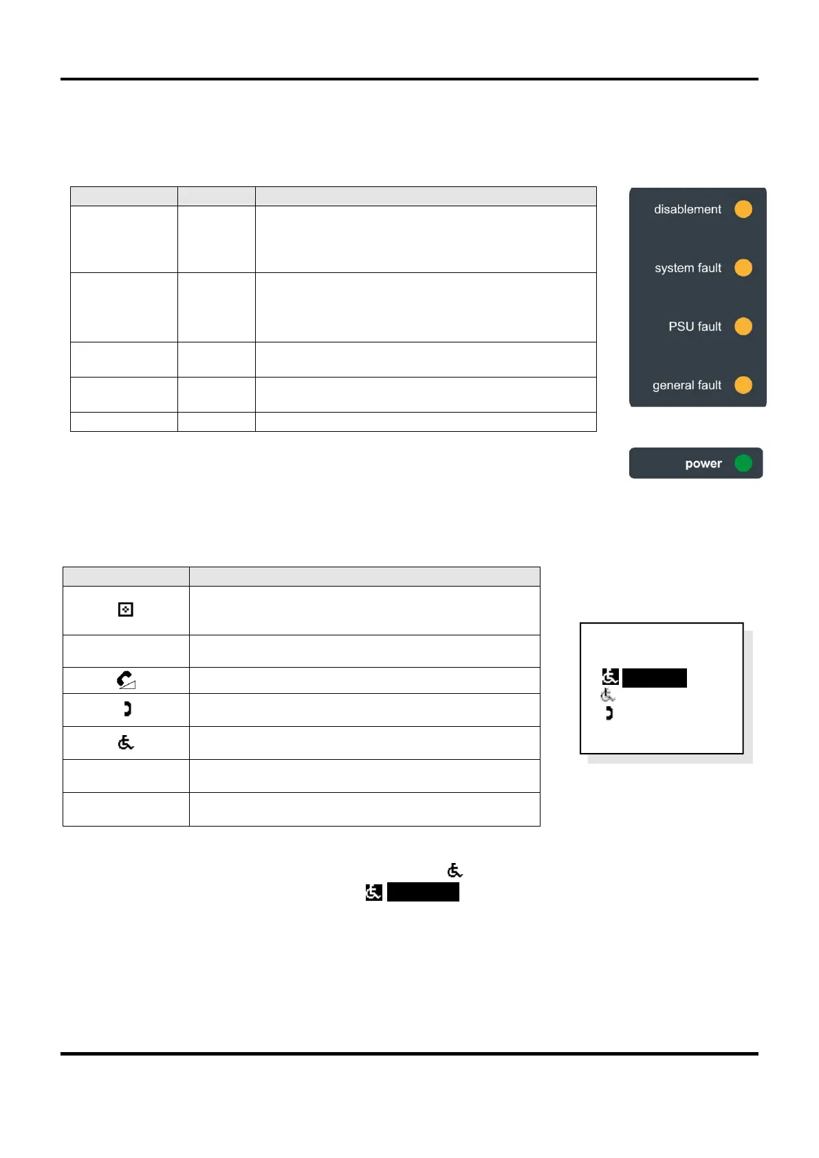
5.1 Wall control unit external indictors
The EVCS is powered up and checking for faults but
the wall control unit is disabled from making, or
receiving calls, until an external trigger is applied, e.g.
from a fire alarm panel. This is NOT a fault indicator.
There is a problem with the microprocessor.
If this indicator cannot be extinguished, there may be
a serious problem with the microprocessor. Contact
the service company responsible for the EVCS.
There is a fault with the Mains power supply or back-
up batteries.
There is a local or remote fault on the EVCS. The
display will show more information.
Power (Mains or battery) is present.
5.2 Wall control unit display
The display shows call status, system information, fault information and uses the following graphic symbols:
Display conventions
Standard / non-active displays are shown normally, e.g. ‘ Extension 2’
Active displays are shown reversed, e.g. ‘> Extension 1’’
The flashing graphic symbol in front of an extension name means this extension is calling the wall control
unit, or the wall control unit is calling the extension. The display’s backlight also flashes red.
MCU Wall Control Unit with handset (ECU-16, ECU-8
or ECU-4)
LCU Wall Control Unit no handset (ECU-8NT)
Desk Control Unit (ECU-224)
Type A (fire telephone) outstation
Type B (disabled refuge) outstation
Disabled persons toilet alarm (DPTA)
The display entry is highlighted, ready to be selected