EasyManua.ls Logo

SIKA TP37 series User Manual

SIKA TP37 series
60 pages
To Next Page IconTo Next Page
Page #1 background imageLoading...
Page #1 background image
Please keep this operating manual for future reference.
If the device is resold, please provide the operating manual along with it.
© SIKA Ba_TP37-TP3M_en 07/2015 .
Temperature calibrators
Series TP37 / TP3M
Types: TP 37 200 E • TP 37 165 E • TP 37 166 E
• TP 37 700 E • TP 3M 165 E • TP 3M 255 E.
Operating manual
(Translation)
Operating manual
.................................................. page 1 - 60

Table of Contents

Question and Answer IconNeed help?

Do you have a question about the SIKA TP37 series and is the answer not in the manual?

SIKA TP37 series Specifications

General IconGeneral
BrandSIKA
ModelTP37 series
CategoryTest Equipment
LanguageEnglish

Summary

0 About this operating manual

Hazard signs and symbols explained

Explains the meaning of various hazard and informational symbols found in the manual.

1 Device description

1.1 Delivery, unpacking and accessories

1.2 Intended use

Burn Hazard Warning

Warns about the danger of touching hot parts and advises on safe handling.

Material Damage Warning

Warns about potential damage to the device from incorrect use of inserts or media.

2 Safety Instructions

Qualified personnel requirements

Specifies the necessary qualifications and awareness for personnel operating the device.

General safety instructions

Covers national regulations, workplace safety, and proper operating environment conditions.

Special safety instructions

2.1 Safety instructions for calibration liquids

3 Construction, Function and Test Task

3.1 Construction

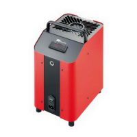
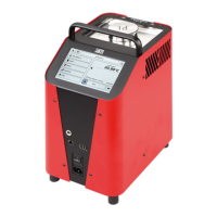
Describes the physical components and design of the calibrator, including housing and internal parts.

3.2 Function

Method of working

Details the operational procedure, including inserting inserts and starting the heating/cooling process.

3.3 Test tasks

4 Commissioning and operation

4.1 Operating conditions

Specifies requirements for installation site, ventilation, clearance, and safe operational positioning.

4.2 Electrical connection

4.3 Preparing of the calibrator

4.3.1 Dry block calibrator

4.3.2 Calibrator for infrared thermometer

4.3.3 Calibrator for surface temperature sensors

4.3.4 Micro bath calibrator

CAUTION! Safety valve!

Warns about the safety valve on the transport cover releasing hot steam.

4.3.4.1 Notes on calibration liquid

4.3.4.2 Information on filling amounts

Incorrect measurement or material damage risk

Warns against exceeding maximum fill levels to prevent measurement errors or damage.

4.3.4.3 Filling the micro bath

4.4 Switching on, cool down and switching off

Switching off procedures

Block temperature warning before switch-off

Warns about potential calibrator damage if switched off outside the safe temperature range.

5 Operation

5.1 Main window

5.2 Configuration range

5.3 Window structure, operating elements and icons

5.3.1 Operating elements

5.3.2 Toolbar and icons

5.4 Functionality of the calibrator

5.4.2 Manage Function

5.4.3 Configure Function

5.5 Test specimen (DUT - Device under test)

5.5.2 Manage DUT

5.5.3 Configure DUT

5.6 Test Task

Manage Test Task

Configure Test Task

5.6.3 Test point

Behaviour at test end / Safety temperature range

Behaviour at test end

Defines the calibrator's action upon test completion.

Safety temperature range

Sets operational safety limits for temperature.

Calculate test points

5.6.4 Functionality

5.6.5 Test specimen (DUT)

5.7 Calibrator settings

Network settings

5.7.2 Measurement reports

6 Performing Calibration Tests

Pre-testing process checks

Lists pre-test checks including installation, connections, and specimen security.

Starting the testing process

Details how to initiate the calibration test using the start/stop slider.

Testing process completion

7 Troubleshooting Problems

7.1 Return shipment to manufacturer

8 Maintenance and cleaning

8.1 Maintenance

Recalibration recommendations

8.2 Cleaning procedures

Venting grilles for inlet air

Temperature fuse over-temperature warning

Warns that low airflow can trigger the temperature fuse, disabling the unit.

8.3 Recalibration process

8.4 Adjustment capabilities

9 Decommissioning and disposal

10 Technical data

10.2 Heating up and cooling times

10.2.3 TP 3M 165 E

10.2.4 TP 3M 255 E

Related product manuals