1 2 AP09 Datum 04.05.2000 Art.Nr. 78091 Z.Nr. 8665013 Änd.Stand 140/00
Attention: if AP09 then does not function, pro-
grammed values will be lost within 10 to 12
seconds.
• Tighten fastening screws and glue foam rub-
ber seal.
• Discharged batteries should be disposed of
safely.
5. Commissioning
Before the first use of the AP09, please check:
1. correct polarity of supply voltage.
2. correct cable connection and existence of
signals.
Note! Before starting bus operation each unit
must have been allocated its address. If one and
the same address is allocated several times,
bus operation will collapse.
Now the AP09 can be used.If necessary, pro-
gram the AP09's parameters according to your
requirements (see chapter ' Parameter Descrip-
tion'). Check whether the AP09 functions without
problems (see chapter 'Operation/Key’s function').
With built-in battery: Battery is tested automa-
tically during operation. When battery voltage
falls below a certain value, "batt" is displayed
and a corresponding note is made under the
status bit in the AP09's protocol.
Operating modes
Two operating modes are possible.
Stand-alone operation:
Position is controlled from the display. Target
value and other parameters have already been
programmed before via interface.
Bus operation:
The interface allows to operate and control up to
31 AP09. Each AP09's parameters can then be
programmed /modified at any time and position
value indicated.
Attention! In case of bus operation the last AP09
on the bus system (the one located at the end of
the bus array) must be provided with a bus termi-
nating element. This plug-shaped accessory, refe-
rence BAS09, can be purchased from SIKO.
In case of connection type E1, please insert a
150Ω (≥1/8W) resistor between DÜA (green
strand) and DÜB (yellow strand). This can for
example be done by using a terminal block.
Battery change
Only exchange battery when operating volta-
ge is applied. Otherwise, when removing the
battery, the programmed parameters will be lost
after approx. 10 to 12 s.
The battery box is at the rear of the device under
the foam rubber seal. New, ready to be used
battery can be ordered from SIKO under article
code 80331.
To change the battery, please proceed as fol-
lows:
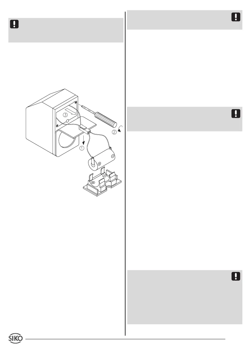
Fig. 6: Battery change
• Remove AP09 from the spindle.
• Apply voltage supply (if it has been discon-
nected previously).
• Prepare new battery.
• Partially remove foam rubber seal (1).
• Battery box (3) can be removed after uns-
crewing the two fixing screws (2).
• Disconnect plug-and-socket connector.
• Insert new battery in reverse order. In case of
wrong polarization
"batt"
will be displayed. Turn
plug-and-socket connector by 180°.
• Strands must be carefully pushed into the unit
and must not be jammed or bent when the
battery box is inserted.
• To check correct battery installation, unit
must be disconnected from supply voltage.
 Loading...