DE04 DE04/1 DE10
Installation Deutsch
DE04 DE04/1 DE10 · Datum 10.12.2012 · Art. Nr. 84260 · Änd. Stand 384/12
6
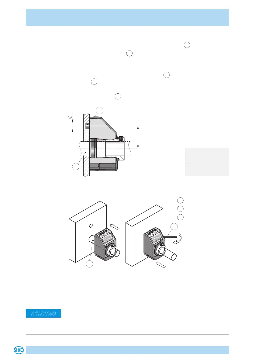
Vorbereitung Montage (Abb. 1, Abb. 2, Abb. 3):
1. Bohrung (øD) auf Abstand (L1) zur Antriebswelle
2
fertigen.
2. Durchmesser der Welle
2
beachten.
Montage (Abb. 1, Abb. 2, Abb. 3):
1. Positionsanzeige bis Anschlag auf Welle
2
schieben. Drehmoment-
stütze
1
in vorhandene Bohrung einführen (verspannungsfreie Mon-
tage). Ein Langloch für die Drehmomentstütze wird empfohlen.
2. Gewindestifte M4
3
anziehen.
Abb. 1: Einbaumaße
Maß øD ø6 (Form A)
ø10
+0.8
(Form B)
Maß L1 22 (DE04, DE04/1)
30 (DE10)
Tab. 1: Einbaumaße
Abb. 2: Montage
Abb. 3: Anzugsmoment
Gewindestift
1
Drehmomentstütze
2
Welle
3
Gewindestift
4.2 Elektrische Installation
Der Einsatzort ist so zu wählen, dass induktive oder kapazitive Störun-
gen nicht auf die Positionsanzeige einwirken können. Das System in mög-
lichst großem Abstand von Leitungen einbauen, die mit Störungen belas-
tet sind.
ACHTUNG
 Loading...


