10 MSK5000+MB500+MR500 Datum 21.09.2010 Art.Nr. 83109 Änd. Stand 318/10
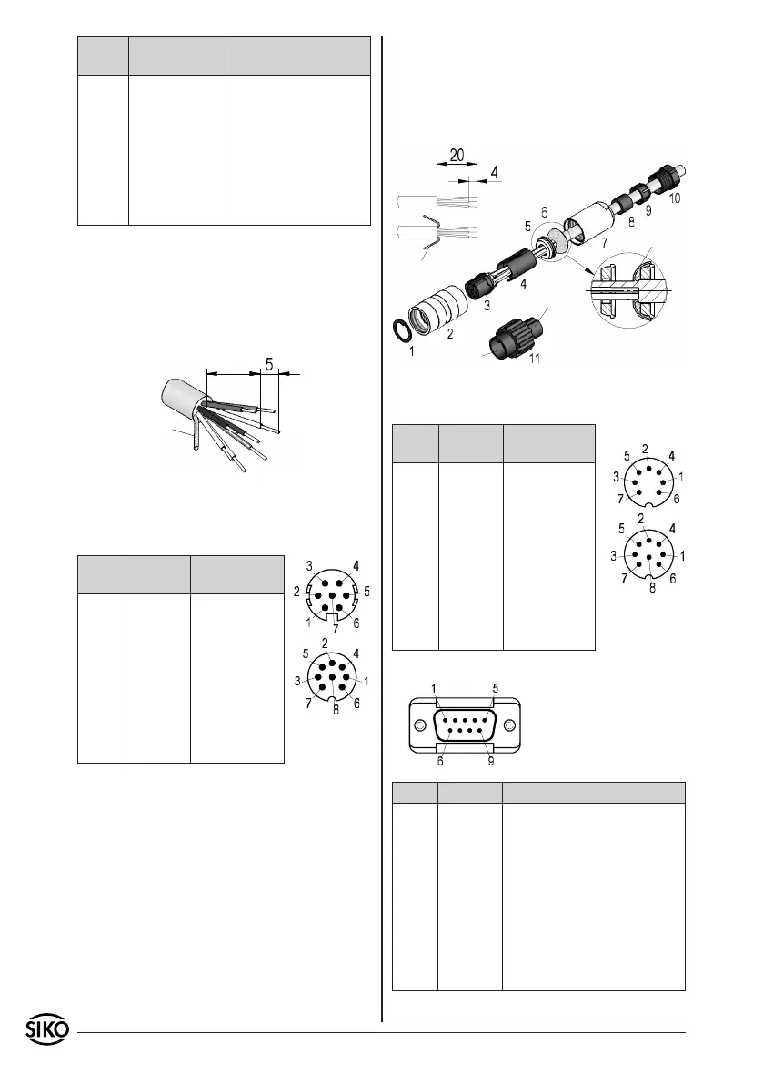
Fig. 8: Connection type E1
as short as
possible
screening
viewing side =
plug-in side
plug pin
viewing side =
plug-in side
plug pin
viewing side = plug-in side
plug pin
Fig. 9: Coupler socket E6
screening
socket
pin
screening
using appropriate tool.
Push part 8 into part 9 and slide both parts
into part 7.
Screw parts 10 and 7 together.
Push part 1 into part 2.
9.
10.
11.
Signal inverted inverted with
reference signal
A red red
B orange orange
I, R - - - blue
+UB brown brown
GND black black
/A yellow yellow
/B green green
/I, /R - - - violet
Remove cable coating.
Open screening and twist it.
Strip stranded wires to a length of 5mm and
twist them.
Pinch stranded wires.
1.
2.
3.
4.
E6: Connection with mit coupler plug and coupler
socket. Plug mounting according to fig. 9.
Signal inverted inverted with
reference signal
A Pin 1 Pin 1
B 2 2
I, R - - - 3
+UB 4 4
GND 5 5
/A 6 6
/B 7 7
/I, /R - - - 8
- - - 3 - - -
Slip parts 6 to 10 over outer cable.
Strip cable.
Turn down screening.
Push part 5 onto ferrules.
Solder wires to part 3 (according connection
diagram).
Open spacer (part 4) and put it over ferrules,
squeeze and push it onto part 3. Slot and keyway
of parts 3 and 4 must align.
Press parts 6 and 5 together; cut prodruding
screening.
Push parts 2 and 7 together and screw part 11
1.
2.
3.
4.
5.
6.
7.
8.
E7: Connection with coupler plug.
Signal inverted inverted with
reference signal
A Pin 1 Pin 1
B 2 2
I, R - - - 3
+UB 4 4
GND 5 5
/A 6 6
/B 7 7
/I, /R - - - 8
- - - 3 - - -
E8: Connection with 9-pole D-SUB plug.
Signal inverted inverted with reference signal
A Pin 1 Pin 1
B 2 2
I, R - - - 3
+UB 4 4
GND 5 5
/A 6 6
/B 7 7
/I, /R - - - 8
- - - 3, 8, 9 9