MSK5000+MB500+MR500 Datum 21.09.2010 Art.Nr. 83109 Änd. Stand 318/10 9
Fig. 6: Definition of the counting direction with
magnetic strip and assemblage sensor/magnetic ring,
gap measure, tolerances
Position of the reference point R = as
stated in the delivery documentation
Position of the reference point E = as stated
in the delivery documentation; min. 0,05m
Magnetic poles -
schema
Unique reference point
Periodical reference point
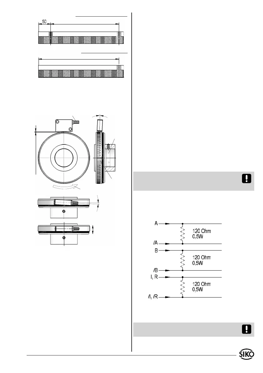
Fig.7: Definition of the counting direction with ma-
gnetic ring and assemblage sensor/magnetic ring,
gap measure, tolerances
Und e rc ut
at the solid
shaft for
tread plug
is recom-
mended
Signal
A before B
Direction of rotation
of magnetic ring
0.1mm ... 2.0mm without reference point
0.1mm ... 1.5mm with reference point
reference
point
Direction of outgoing cable
Admissable deviatoion
middle of tape/sensor:
without ref. point ±2mm
with ref. point ±0.5mm
< 3°
< 3°
RADIAL application MSK5000 with MR500:
(e.g. interference caused by SMPS, motors, cyclic
controls and contactors).
Necessary measures:
Only screened cable should be used. Wire cross sec-
tion is to be at least 0,14mm², max. 0,5mm².
Wiring to the screen and ground (0V) must
be secured to a good point. Ensure that the
connection of the screen and earth is made to
a large surface area with a sound connection to
minimise impedance.
The system should be positioned well away from
cables with interference; if necessary a protective
screen or metal housing must be provided. The
running of wiring parallel to the mains supply
should be avoided.
Contactor coils must be linked with spark sup-
pression.
Supply voltage
The voltages depend on the sensor designs; they
are to be taken from the delivery documentation
and the identification plate.
e.g.: 6,5VDC ... 30VDC
Attention! When connecting sensor and follower
electronics, please do not exceed the max. admis-
sable cable length.
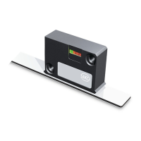
4.1 Connection note acc. to RS422 standard
Please provide the channels with a 120 Ohm ter-
minating resistor.
•
•
•
•
4. Electrical connection
Wiring must only be carried out with power off!
Check all lines and connections before switching
on the equipment!
Interference and distortion
All connections are protected against the effects
of interference. The location should be selected
to ensure that no capacitive or inductive in-
terferences can affect the sensor or the con-
nection lines! Suitable wiring layout and choice
of cable can minimise the effects of interference
•
•
4.2 Connection type
E1: Flying leads.
Attention! Tinned strands must not used in com-
bination with screw/clamp connections.