8 MSK5000+MB500+MR500 Datum 21.09.2010 Art.Nr. 83109 Änd. Stand 318/10
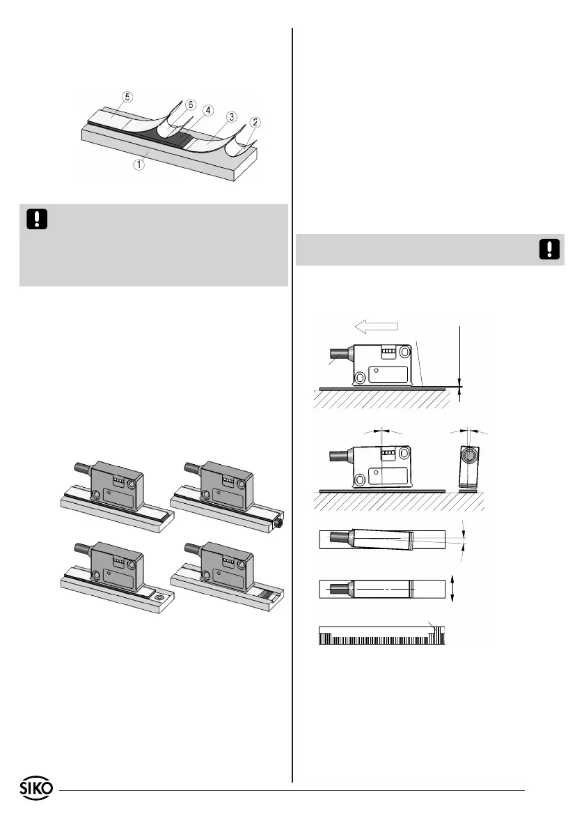
Fig. 1: Mounting of the magnetic strip
Fig. 2 Fig. 3
Fig. 4 Fig. 5
0.1mm ... 2.0mm wit-
hout reference point
0.1mm ... 1.5mm with
reference point
Gap sensor/magnetic strip
Maximum alignment error
active side
Direction of
outgoing cable
Travel direction
Signal
A before B
Position of the reference point relating
to the marking on the magnetic strip.
Admissable deviatoion
middle of tape/sensor:
without ref. point ±2mm
with ref. point ±0.5mm
< 1°
< 3°
< 3°
MBxxxx GEK WT RP NNNNNN
Fix cover strip (both ends should slightly over-
lap).
Also fix cover strip's ends to avoid unintenti-
onal peeling.
•
•
3.3 Mounting of the magnetic sensor MSK5000
The magnetic sensor MSK5000 can be fastened by
using two bolts M3 over the elongated holes. We
recommend to use the enclosed fixing screws and
washer springs (fastening torque design K=0,25Nm,
design M+AM=1Nm).
Cables should be layed in such a way that there
is no danger of damaging. Provide tension relief
and drag chain or casing, if necessary.
Observe the correct alignment with regard
to the counting direction (fig. 6 and 7). This
does not apply if the counting direction can be
reversed in the electronic interpretation (e.g. in
SIKO's magnetic-strip displays).
Attention! The tolerance and gap measures must
be observed over the whole measuring length.
LINEAR application MSK5000 with MB500:
•
•
Attention! Do not expose the system to magne-
tic fields. Any direct contact of the magnetic strip
with magnetic fields (e.g. adhesive magnets or
other permanent magnets) is to be avoided. Sen-
sor movements during power loss are not captured
by the follower electronics.
Mounting examples
Mounting with chamfered ends (fig. 2) is not re-
commended unless the strip is installed in a safe
and protected place without environmental influ-
ences. In less protected mounting places the strip
may peel. There we recommend mounting accord.
to fig. 3 and 4.
Mounting in a groove (fig. 5) best protects the
magnetic strip. The groove should be deep enough
to totally embed the magnetic strip.
3.2 Mounting of the magnetic ring MR500
Slide magnetic ring MR500 onto the shaft and
then tighten grub screw M6 to fix it to the shaft.
Ensure sliding fit between shaft and MR500.
Mount MR500 without force and without strain.
Possible forces should go to the metal flange.
Avoid knocks on the magnetic ring.
Provide for a relief groove in the solid shaft
(see fig. 7).
•
•
•