MSK5000+MB500+MR500 Datum 21.09.2010 Art.Nr. 83109 Änd. Stand 318/10 11
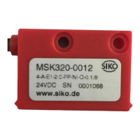
A B I/R Power
metal housing
Power A B I/R
plastic housing
viewing side =
plug-in side
plug pin
V max. =
(in mm/s)
Resolution mm
Pulse interval s
x 0.8
Example:
Resolution: 0,01mm
Pulse interval: 2,5µs
V =
0,01
0,0000025
x 0.8 = 3200mm/s
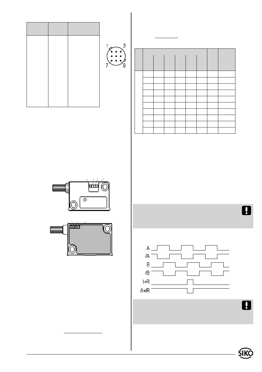
E14X: Connection with 9-pole plug.
Signal inverted inverted with
reference signal
A Pin 1 Pin 1
B 2 2
I, R - - - 3
+UB 8 8
GND 7 7
/A 4 4
/B 5 5
/I, /R - - - 6
- - - 3,6 - - -
shielding 9 9
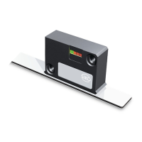
5. Commissioning
Following proper installation and wiring, the
measuring system can be commissioned by
switching on the supply voltage. After switching
on, the device initializes itself independently. The
"power" LED (green) in the sensor housing lights
up. While the magnetic sensor travels over the
magnetic strip, the LEDs A, B and I/R (red) are
lighting accordingly.
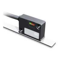
The measuring system MSK5000/MB500 is a com-
ponent of an incremental measuring system which
must be referenced at a defined position (refe-
rence point) for absolute measurement. For this
purpose, the reference signal must be linked to
the signal of a reference value encoder (e.g. pro-
ximity switch).
6. Travel speeds (m/s)
Formula for calculating the travel speed:
Resolution mm
Pulse inter-
val (µs)
Counting
frequency
(kHz)
0,001 0,005 0,010 0,025 0,050 0,100
Travel speed m/s
0,01 0,06 0,12 0,30 0,61 1,21 66,00 3,79
0,03 0,13 0,25 0,63 1,25 2,50 32,00 7,81
0,05 0,25 0,50 1,25 2,50 5,00 16,00 15,63
0,10 0,50 1,00 2,50 5,00 10,00 8,00 31,25
0,20 1,00 2,00 5,00 10,00 20,00 4,00 62,50
0,32 1,60 3,20 8,00 16,00 25,00 2,50 100,00
0,80 4,00 8,00 20,00 25,00 25,00 1,00 250,00
1,60 8,00 16,00 25,00 25,00 25,00 0,50 500,00
3,20 16,00 25,00 25,00 25,00 25,00 0,25 1000,00
4,00 20,00 25,00 25,00 25,00 25,00 0,20 1250,00
7. Output signals
The translation module translates the length
information of the magnetic sensor into incre-
mental output signals with real-time processing of
the output signals.
Please note that pulses having the width of
the pulse interval set can occur at standstill of
the device (caused by the internal interpolation
method).
Attention! When dimensioning the follow-on
electronics please take care that it is adjusted
to the set pulse interval or counting frequency,
respectively.
Signal sequence
Note: The position of the index or reference sig-
nal I+R, respectively, with respect to signals A
and B is not defined and can deviate from the
drawing.