Silca S.p.A. Copyright by Silca S.p.A. – All rights reserved 1 / 2
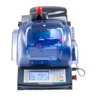
Marker 2000
F.A.Q.
www.silca.biz
Marking depth is too shallow or too deep. Marking punch ring is not adjusted properly.
A. Changing settings clockwise will decrease and counter clockwise will increase the punching pressure.
Text is marked in an area not selected with the dial. The data registered on the information screen
regarding slide number is different than the box selected from
the dial.
A. Check the box selected on the dial and verify the same slide number is selected on the information
screen. If not, change this slide number with the + or - key.
When marking, the object moves from the original position, the object is not being held tightly, or the
object will not fit in the clamp correctly. The object is not being held correctly.
A. Make sure that the lateral adjustment clamp is positioned properly. If not, loosen the locking knob and
adjust accordingly.
B. Check that the vertical jaw slide is in the correct position. For more clearance, loosen the knob and re-
position. Make sure the knob is tight before marking.
Unreadable text. Auto-format is not selected.
A. Check to see if the Auto-format option located on the general information screen is selected (marked
with an X). If not, select it to make sure that scaling will occur.
When preparing to mark an object, the display reads, Marking in Progress, Clamp out of position.
Clamp is in the forward (tracking position).
A. Push clamp to the back (marking position).
If the red laser light marking area indicator does not work.
A. Lay machine down on its back.
B. Loosen screw in tracking unit until it stops.
C. Remove wheel (tracking disk).
D. Remove two connectors on the (right) side.
E. Loosen top two (big) screws (allen).
F. Pull out tracking unit (tracking block) aluminium or grey colour.
G. Remove wires to unit and ground wires.
H. Ground wire is in the back, other wire for marker is at the bottom of the tracking unit.
I. It is important to recuperate the tracking wheel (disc).
J. When finished fixing tracking unit, snap on your replacement unit, then assemble screws and wires back in
place.
Replacing marking punch assembly or (punch shaft). Symptom is cracked shaft (marking punch).
A. Remove back bracket (block), at this time machine should be laid down on the back.
B. Loosen (4) large allen screws on the marker plate (block).
C. Take (2) wires off on the right side.
D. Remove unit, be careful while moving unit, there are (4) springs in the back that may pop out if you are
not careful.
E. Remove marking punch. Use an allen wrench to go through the top to take out marking punch.
F. Loosen screws (allen) on marking punch.
G. Remove allen screw in center and punch shaft up from bottom.
H. Insert new shaft with notch to left while facing machine.
Changing the magnet.
A. Follow previous steps.
B. Loosen ring nut and (4) allen screws and the main spring.
C. Loosen (3) allen screws on magnet assembly.
D. Remove magnet-detach bottom (2) wires first.
E. Put new magnet in and wires to desired length that is needed.
F. Largest pin of the (5) goes in the front (top).
G. Ring nut must be flush when reassembled.