EasyManua.ls Logo

Silca MARKER 2000 - User Manual

Silca MARKER 2000
58 pages
Print Icon
To Next Page IconTo Next Page
Loading...
®
Operating manual
D430498XA
vers .
4.0

Table of Contents

Other manuals for Silca MARKER 2000

Questions and Answers

  • J
    Javier ThompsonAug 14, 2025
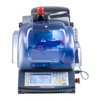
    What to do if Silca MARKER 2000 Power Tool displays 'ALARM Temperature is over max. foreseen Turn off Marker!' message?
    • J
      Jacqueline DodsonAug 14, 2025
      If you see 'ALARM Temperature is over max. foreseen Turn off Marker!' on the display, first check if the cooling fan is working. If the fan works, switch off the Silca Power Tool and contact a Silca Service Centre.
  • E
    Elijah RiveraAug 18, 2025
    What to do if Silca MARKER 2000 Power Tool displays 'CHECK FUSE F1' message?
    • M
      Michael EspinozaAug 18, 2025
      If the Silca Power Tool displays 'CHECK FUSE F1', check the fuse. If it's not burnt out, replace the electronic control circuit board. If the fuse is burnt, replace it and turn on the machine. If the message reappears, replace the electronic control circuit board. If the message disappears and the machine works, continue operations, as the fuse likely protected the machine from mains electricity variations.
  • Y
    ymooreAug 21, 2025
    What to do if Silca Power Tool displays 'ALARM Short circuit' message?
    • J
      Jonathan BryanAug 21, 2025
      If the Silca Power Tool displays 'ALARM Short circuit', disconnect the wire (7) from the control circuit board. Turn on the machine: if the message remains, replace the electronic control circuit board; if the message disappears, replace the wire (7).
  • D
    drossAug 25, 2025
    How to fix a marking punch that is not working on Silca MARKER 2000 Power Tool?
    • J
      James GriffinAug 25, 2025
      If the marking punch on your Silca Power Tool isn't working, start by checking fuse F3 on the electronic control circuit board. Also, inspect the wiring between the electronic control circuit board and the magnet. If those are fine, try replacing the magnet or the electronic control circuit board.
  • E
    Erin LewisAug 28, 2025
    How to troubleshoot a tracking laser that is not illuminating on a Silca MARKER 2000?
    • L
      lsmithAug 28, 2025
      If the tracking laser on your Silca Power Tool isn't illuminating, first check fuse F1 on the electronic control circuit board. Ensure the disk is properly inserted into the tracking block and the clamp isn't in the marking position. Check the safety microswitch operation on the tracking unit using an ohmmeter. Also, verify the wiring between the electronic control circuit board and the tracking unit. Perform a TEST 102 to check the clamp detector microswitch operation. If problems persist, replace the tracking unit or the electronic control circuit board.
  • M
    munoznicoleAug 31, 2025
    What to do if the keyboard is not working on Silca MARKER 2000 Power Tool?
    • J
      Jose SparksAug 31, 2025
      If the keyboard on your Silca Power Tool isn't working, first check the wiring between the electronic control circuit board and the keyboard. If the wiring is intact, try replacing the electronic control circuit board or the keyboard itself.
  • M
    Michael WoodSep 3, 2025
    Why is the working head not moving on my Silca Power Tool?
    • E
      Elizabeth WarnerSep 3, 2025
      If the working head on your Silca Power Tool isn't moving, check fuse F3 on the electronic control circuit board. Also, inspect the wiring between the electronic control circuit board and the motors. If problems persist, replace the electronic control circuit board.
  • S
    Scott PittsSep 6, 2025
    What to do if working head is not returning to the idle position on Silca Power Tool?
    • J
      Jacob ColemanSep 6, 2025
      If the working head on your Silca Power Tool isn't returning to the idle position, check fuse (F1) on the control circuit board. If the display shows “CHECK FUSE F1”, carry out a TEST 101 on the X and Y axis sensors operation.
  • H
    Heather LongSep 10, 2025
    How to troubleshoot a Silca MARKER 2000 when it's on but the display shows no message?
    • J
      Jonathan TylerSep 12, 2025
      If the Silca Power Tool machine is on but there is no message on the display, check the display connection. If that doesn't work, replace the display. If it still fails, check the general fuses in the power socket and the fuses on the electronic control circuit board. As a last resort, replace the electronic control circuit board.

Summary

GENERAL

USE

Information on the intended use of the electronic marker for marking metals and other materials.

INCORRECT USE

Details on incorrect uses of the machine and the manufacturer's disclaimer of responsibility.

FURTHER RISKS

Statement confirming no further risks arise from the use of the MARKER 2000.

PROTECTION AND SAFETY PRECAUTIONS FOR THE OPERATOR

Overview of safety features, power supply, start-up, maintenance, and machine identification.

1 MACHINE DESCRIPTION

1.1 Main Features

Details on the key features of the MARKER 2000, including movement, clamp, punch, tracking, marking, display, and keyboard.

1.2 Working parts

Identification and description of the main working parts of the MARKER 2000 machine.

1.3 Technical data

Technical specifications of the MARKER 2000, including power, dimensions, and noise levels.

1.4 Accessories provided

List of accessories included with the MARKER 2000 for operation and maintenance.

2 TRANSPORT

2.1 Packing

Description of the packing materials and methods used to ensure safe transportation of the MARKER 2000.

2.2 Transport

Information regarding transport symbols on the packaging and advice on using packing for transport.

2.3 Unpacking

Step-by-step instructions for safely unpacking the MARKER 2000 from its packaging.

2.4 Machine handling

Guidance on how to handle and position the MARKER 2000 after it has been unpacked.

3 MACHINE INSTALLATION AND PREPARATION

3.1 Checking for damage

Instructions for inspecting the MARKER 2000 for any damage prior to installation.

3.2 Environmental conditions

Recommended environmental conditions, such as temperature and humidity, for machine operation.

3.3 Positioning

Guidelines for correctly positioning the MARKER 2000 on a stable surface.

3.4 Description of work station

Overview of the operator's controls and workspace for the MARKER 2000.

3.5 Graphics

Information regarding graphics and warning labels required for machine operation.

4 REGULATION AND USE OF THE MACHINE

4.1 Clamp

Explanation of the 'C1' clamp system for securing and regulating keys.

4.2 Securing the keys

Detailed steps for positioning and securing keys using the clamp mechanism.

4.3 Tracking

Explanation of the tracking system for identifying and positioning the marking zone.

4.4 Marking punch regulation ring

Instructions on how to adjust the marking punch depth using the regulation ring.

4.5 Marking

Description of the marking method using dots and available fonts.

5 INSTALLATION AND PRELIMINARY OPERATIONS [SET-UP]

SET-UP [F5]

Procedure for initiating the machine's setup menu via the F5 key.

LANGUAGE

Instructions for selecting the machine's operating language.

KEYBOARD

Steps to configure the connected keyboard type for the machine.

SERIAL NUMBER

How to enter and confirm the machine's serial number.

[F1] help

Explanation of the F1 key's function for accessing help and guides.

6 MARKING [F2]

6.1 New Model [F3]

Procedure for creating a new marking model, including text and parameters.

6.1.1 Definition of model parameters

Defining parameters like zone, clamp, slide, and orientation for a marking model.

6.1.2 String definition [F7] - text entry

Entering text strings for marking, with options for automatic formatting.

6.1.2-a Attributes definition [F7]

Customizing text attributes like height, alignment, and font for marking.

6.1.2-b Entering fixed strings [F3]

Incorporating pre-defined text strings into a marking model.

6.1.2-c Entering the automatic counters [F4]

Adding progressive counters to the marking text.

6.1.2-d Entering symbols [F2]

Adding special symbols to the marking text.

6.1.2-e Fixed lines (CTRL+F2)

Defining fixed lines of text within the marking area.

6.1.3 Tracking [F8]

Centering the glass slide over the key using the tracking function.

6.1.4 Save model

Saving the created marking model with a name.

6.1.5 Marking [F10]

Executing the marking operation on a key using the F10 function.

6.1.5-a Marking by counters

Marking operations that incorporate automatic counters.

6.1.6 Glass slide customization [F2]

Customizing or defining glass slides for specific marking areas.

6.1.7 Clamp configuration [F3]

Configuration settings for the optional clamp 'A5'.

6.1.8 Counters [F4]

Accessing the counter definition menu for marking parameters.

6.1.9 Entering a new tracking zone [F5]

Setting up multiple tracking zones for different markings on a single key.

6.1.10 Deletion of a tracking area [F6]

Procedure for deleting a previously defined tracking area.

6.2 Fixed strings [F4]

Managing pre-defined text strings for use in marking models.

6.2.1 Deletion of fixed strings [F5]

Removing fixed strings from the system's memory.

6.3 List of models [F2]

Accessing and managing the list of created marking models.

6.3.1 Altering the model [F10]

Modifying parameters and text of an existing marking model.

6.3.2 Copy model [F2]

Duplicating an existing model to create a new one with a different name.

6.3.3 Delete model [F5]

Removing a specific model from the list of stored marking models.

6.4 SPECIAL FUNCTIONS

Details on special functions available for marking operations.

6.4.1 Entering fixed strings [F3]

Including pre-defined text strings from a list into a new marking model.

6.4.2 Entry of automatic counters [F4]

Setting up progressive alphanumeric or double progressive counters for marking.

6.4.3 Entering symbols [F2]

Inserting special symbols into the marking text, one per line.

6.4.4 Fixed lines (CTRL+F2)

Defining fixed lines of text within a marking area, including forcing subdivisions.

6.4.5 Special characters

Using special characters from the ANSI table via key combinations.

6.5 Data from PC [F3]

Managing data transfer between the PC and the MARKER 2000.

6.5.1 Connecting MARKER 2000 to a Personal Computer

Steps to connect the MARKER 2000 to a PC for data transfer.

6.5.2 Transfer of data from Marker 2000 to Personal Computer

How to copy data from the marking machine memory to a PC.

7 SETTING THE ZEROES [F8]

7.1 Regulating the sensors

Procedure for adjusting the X and Y axis sensors for precise positioning.

8 TEST FUNCTIONS

DIAGNOSTICS [F4]

Using the diagnostics function to check machine parts for faults.

Test 100 = Motors

Testing the X and Y axis motors by activating them via the controls.

Test 101 = Sensors

Verifying the functionality of the X and Y axis limit switch sensors.

Test 102 = Clamp microswitch

Checking the clamp detection microswitches for proper operation.

Test 103 = Magnet

Testing the magnet by sending an impulse to the marking punch.

Test 104 = Laser

Testing the laser emission for projection visibility.

Test 105 = Temperature

Monitoring the temperature of the electronic control circuit board.

Test 106 = Digital outlets

Testing digital outlets for optional functions.

Test 107 = Inlets 1

Testing inlets 1 for optional functions.

Test 108 = Inlets 2

Testing inlets 2 for optional functions.

9 MAINTENANCE

9.1 Trouble shooting

Guide to identifying probable causes for machine faults and errors.

Replacing the tracking unit

Step-by-step guide for replacing the tracking unit.

Replacing the marking punch

Instructions for replacing the marking punch.

Removing the upper cover

Procedure to remove the top cover for maintenance access.

Replacing the belts and adjusting tension

How to replace belts and adjust tension on the Y and X axis.

REPLACING THE X AXIS BELT

Detailed steps for replacing the belt on the X axis.

Replacing the display

Instructions for replacing the machine's display unit.

Checking and replacing fuses

How to check and replace fuses in the MARKER 2000.

3 fuses: F1, F2 and F3

Details on the three fuses (F1, F2, F3) located on the electronic board.

Replacing the control circuit board

Step-by-step guide for replacing the electronic control circuit board.

Replacing and positioning the sensors

Instructions for replacing and positioning the Y axis sensors.

Replacing the X axis sensor

Instructions for replacing and positioning the X axis sensors.

10 ELECTRICAL DIAGRAMS

ELECTRONIC CONTROL CIRCUIT BOARD

Diagram showing the layout of the electronic control circuit board and its connectors.

1 display connector

Wiring diagram for the display connector.

2 keyboard connector

Wiring diagram for the keyboard connector.

3 serial connector RS 232 computer

Wiring diagram for the serial RS 232 computer connector.

4 clamp detection microswitch connector

Wiring diagram for the clamp detection microswitch connector.

5 tracking laser control connector

Wiring diagram for the tracking laser control connector.

6 ventilator connector

Wiring diagram for the ventilator connector.

7 inlet-outlet connector

Wiring diagram for the inlet-outlet connector.

8 X axis sensor connector

Wiring diagram for the X axis sensor connector.

9 Y axis sensor connector

Wiring diagram for the Y axis sensor connector.

10 power transformer connector

Wiring diagram for the power transformer connector.

11 X axis motor connector

Wiring diagram for the X axis motor connector.

12 Y axis motor connector

Wiring diagram for the Y axis motor connector.

13 magnet control connector

Wiring diagram for the magnet control connector.

11 WASTE DISPOSAL

Waste deriving from the machine

Information on waste produced by the MARKER 2000 during use.

Machine

Notes on the machine's re-usability and recyclability.

Packing

Disposal instructions for the packing materials.

INFORMATION FOR USERS

User information regarding Waste from Electric and Electronic Appliances (RAEE).

12 ASSISTANCE

12.1 How to request service

Guide on how to request service and understand the guarantee terms.

Silca MARKER 2000 Specifications

General IconGeneral
BrandSilca
ModelMARKER 2000
CategoryPower Tool
LanguageEnglish

Related product manuals