CP2102-EK
Rev. 0.5 5
6.2. UART Signals (J1, J2)
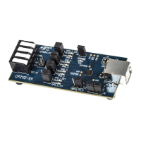
A RS232 transceiver circuit and DB-9 connector (J1) are provided on the evaluation board to connect the CP2102
virtual serial port to external serial devices. See Table 2 for the RS232 J1 pin descriptions. The J2 connector is pro-
vided to facilitate direct access to the CP2102’s UART signals. Shorting blocks on J2 are required to connect the
UART signals to J1. See Table 3 for J2 pin descriptions.
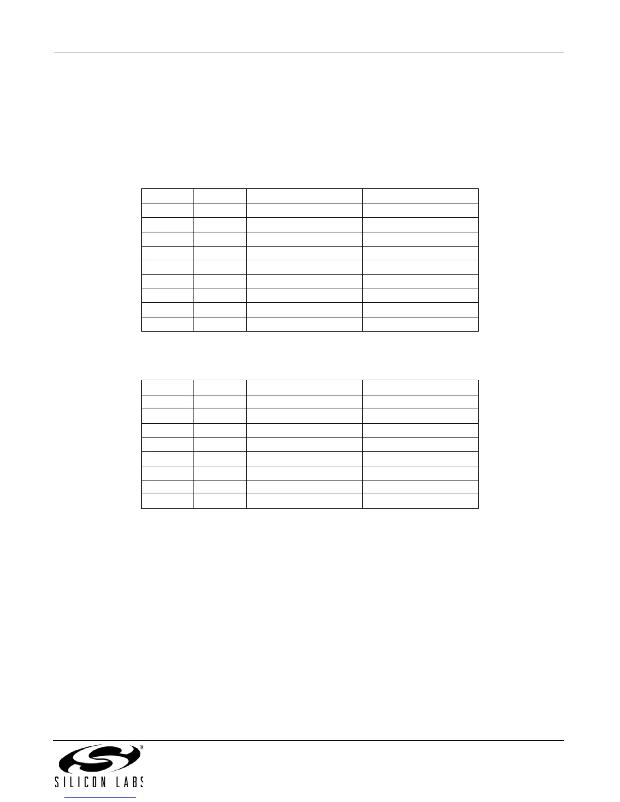
Table 2. RS232 Pin Descriptions
Pin Signal CP2102 Direction Description
1 DCD Input Data Carrier Detect
2 RXD Input Receive Data
3 TXD Output Transmit Data
4 DTR Output Data Terminal Ready
5 GND Ground
6 DSR Input Data Set Ready
7 RTS Output Request to Send
8 CTS Input Clear to Send
9 RI Input Ring Indicator
Table 3. J2 Pin Descriptions
Pins Signal CP2102 Direction Description
1-2 TXD Output Transmit Data
3-4 RXD Input Receive Data
5-6 DTR Output Data Terminal Ready
7-8 RI Input Ring Indicator
8-10 DCD Data Carrier Detect
11-12 DSR Input Data Set Ready
13-14 CTS Input Clear to Send
15-16 RTS Output Request to Send


 To Next Page