EasyManua.ls Logo

Silicon Laboratories EFR32FG23 - User Manual

Silicon Laboratories EFR32FG23
28 pages
Print Icon
To Next Page IconTo Next Page
Loading...
UG508: EFR32FG23 Dev Kit User's Guide
The EFR32FG23 Dev Kit is a low cost, small form factor prototyp-
ing and development platform for the EFR32FG23 Wireless Sys-
tem-on-Chip.
The board is small, cost effective, and feature rich. It is an ideal platform for developing
energy-friendly connected IoT devices based on the EFR32FG23.
A built in SEGGER J-Link debugger ensures easy debugging through the USB Micro-B
connector.
TARGET DEVICE
EFR32FG23 Wireless System-on-Chip
(EFR32FG23B010F512IM48)
32-bit ARM® Cortex®-M33 with 78 MHz
maximum operating frequency
512 kB flash and 64 kB RAM
Energy-efficient radio core with low
active and sleep currents
Integrated PA with up to 20 dBm (sub-
GHz) TX power
Robust peripheral set and 31 GPIO
KIT FEATURES
SMA connector for antenna connection
5-digit 7-segment LCD
Relative humidity and temperature sensor
LC sensor for metal detection
User LED and 2 push buttons
2.54 mm breakout pads for GPIO access
SEGGER J-Link on-board debugger
Virtual COM port
Packet Trace Interface (PTI)
Mini Simplicity connector for AEM and
packet trace using external Silicon Labs
debugger
USB or coin cell battery powered.
SOFTWARE SUPPORT
Simplicity Studio™
ORDERING INFORMATION
FG23-DK2600A
silabs.com | Building a more connected world. Rev. 1.1
Question and Answer IconNeed help?

Do you have a question about the Silicon Laboratories EFR32FG23 and is the answer not in the manual?

Summary

Introduction

1.1 Kit Contents

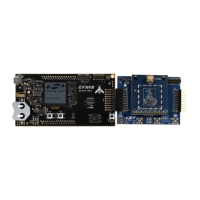
Lists items included in the development kit box.

1.2 Getting Started

Provides links for initial setup and guidance.

1.3 Hardware Content

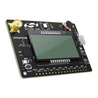
Details the key hardware components of the development kit.

1.4 Kit Hardware Layout

Illustrates the physical arrangement of components on the dev kit.

Specifications

2.1 Recommended Operating Conditions

Details typical operating conditions and design limits for the dev kit.

Hardware

3.1 Block Diagram

Provides an overview of the dev kit's hardware components and connections.

3.2 Power Supply

Explains the different power sources and architecture for the dev kit.

3.3 EFR32 FG23 Reset

Describes the various methods to reset the EFR32FG23 microcontroller.

3.4 Peripherals

Lists and describes the peripherals available on the EFR32FG23 Dev Kit.

3.4.1 Segment LCD

Details the 4x10 segment LCD display and its connections.

3.4.2 Si7021 Relative Humidity and Temperature Sensor

Explains the Si7021 sensor for humidity and temperature measurement.

3.4.3 Push Buttons and LED

Describes the user buttons (BTN0, BTN1) and LED (LED0) on the kit.

3.5 On-board Debugger

Details the integrated SEGGER J-Link debugger and its features.

3.6 Connectors

Introduces the various connectors available on the dev kit.

3.6.1 Breakout Pads

Explains the 18 breakout pads for peripheral and add-on board connections.

3.6.2 Mini Simplicity Connector

Details the 10-pin Mini Simplicity connector for external debuggers.

3.6.3 Debug USB Micro-B Connector

Describes the USB Micro-B connector for code upload and debugging.

Debugging

4.1 On-board Debugger

Details the functionality of the integrated SEGGER J-Link debugger.

4.2 External Debugger

How to use external debuggers with the Mini Simplicity Connector.

4.3 Virtual COM Port

Explains the virtual COM port for serial communication.

Radio

5.1 RF Section

Provides an introduction to the RF section schematic and components.

5.1.1 Description of the Sub-GHz RF Matching

Explains the RF matching network for Sub-GHz communication.

5.1.2 RF Section Power Supply

Details the power supply for the RF section, including the DC-DC converter.

5.1.3 RF Matching Bill of Materials

Lists the components for the RF matching network.

5.2 EMC Regulations

Covers electromagnetic compatibility regulations for the device.

5.2.1 ETSI EN 300-200-1 Emission Limits for the 868-868.6 MHz Band

Specifies emission limits according to ETSI EN 300-200-1 for the 868 MHz band.

5.2.2 FCC15.247 Emission Limits for the 902-928 MHz Band

Details FCC 15.247 emission limits for the 902-928 MHz band.

5.3 Relaxation with Modulated Carrier

Explains relaxation factors for modulated carrier measurements.

5.4 RF Performance

Presents performance data related to the radio frequency capabilities.

5.4.1 Conducted Power Measurements

Reports conducted power measurement results for different frequency bands.

5.4.1.1 Conducted Measurements in the 868 MHz Band

Shows typical output spectrum for conducted power at 868 MHz.

5.4.1.2 Conducted Measurements in the 915 MHz Band

Shows typical output spectrum for conducted power at 915 MHz.

5.4.2 Radiated Power Measurements

Explains radiated power measurement methodology and results.

5.4.2.1 Radiated Measurements in the 868 MHz Band

Details radiated power measurements for the 868 MHz band.

5.4.2.2 Radiated Measurements in the 915 MHz Band

Details radiated power measurements for the 915 MHz band.

5.4.2.3 Antenna Pattern Measurements in the 868 MHz Band

Shows typical antenna radiation patterns for the 868 MHz band.

5.4.2.4 Antenna Pattern Measurement in the 915 MHz Band

Shows typical antenna radiation patterns for the 915 MHz band.

5.5 EMC Compliance Recommendations

Provides recommendations for achieving EMC compliance.

5.5.1 Recommendations for 868 MHz ETSI ETSI EN 300-200-1 compliance

Recommendations for ETSI EN 300-200-1 compliance at 868 MHz.

5.5.2 Recommendations for 915 MHz FCC 15.247 compliance

Recommendations for FCC 15.247 compliance at 915 MHz.

Schematics, Assembly Drawings, and BOM

Kit Revision History

Board Revision History and Errata

8.1 Board Revision History

Information on finding and understanding board revision history.

8.2 Errata

Lists any known issues or corrections for the board.

Document Revision History

Silicon Laboratories EFR32FG23 Specifications

General IconGeneral
BrandSilicon Laboratories
ModelEFR32FG23
CategoryMicrocontrollers
LanguageEnglish

Related product manuals