2685
8
GB
The settings, indicated in the table at page 6, refer to the
burner with its cover fitted and combustion chamber with
depression zero.
These regulations are purely indicative. Each installation
however, has its own unpredictable working conditions: actual
nozzle ou t p ut; po sitive or ne g a t i v e pres s u r e in th e
combustion-chamber, the need of excess air, etc.
All these conditions may require a different air-damper setting.
It is important to take account of the fact that the air
output of the fan differs according to whether the
burner has its cover fitted or not.
Therefore we recommended to proceed as follows:
➤ Adjust the air damper as indicated in the table at page 6.
➤ Mount the cover.
➤ Check smoke number and CO
2
.
➤ Should it become necessary to modify the air output,
remove the cover by loosening the screw, adjust the air damper, remount the cover and finally recheck
the smoke number.
4.6 PUMP PRESSURE
11 bar: The pump leaves the factory set at this value.
14 bar: Improves flame retention; it is therefore suitable for ignitions at low temperatures.
4.7 BURNER START-UP CYCLE
Lock out is indicated by a lamp on the control box (3, fig. 1, page 1).
4.8 ADJUSTMENTS, TO AVOID FLAME - DETACHMENT, AT BURNER - IGNITION
This inconvenience can occur, when the temperature of the gas-oil decreases below + 5 °C.
1) CORRECT POSITIONING OF THE ELECTRODES, (see fig. 11, page 7).
2) PUMP - SETTING
The pump is factory set, at a pressure of 11 bar.
When the temperature of the gas-oil decreases below + 5 °C, increase the pressure to 14 bar.
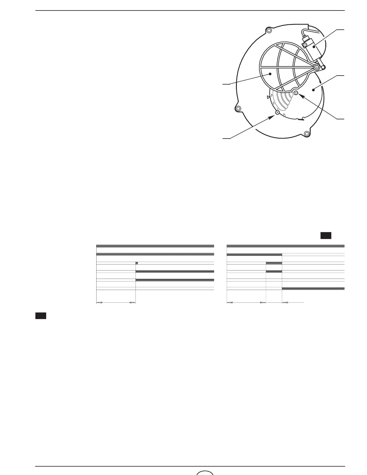
3) COMBUSTION-HEAD SETTING
Regulate the combustion-head one set-point further ahead than indicated in the instructions.
Example: the instructions require to set the combustion-head on set-point 3.
Instead, the setting is made on set-point 4.
4) FAN - AIR DAMPER ADJUSTMENT
Adjust the air damper of the fan, such as to obtain a smoke-number not inferior to 1.
(i.e. a combustion with the lowest possible excess-air).