47
EN
With the curve supplied in the kit, the
maximum horizontal length of the duct
must be no more than 6 metres.
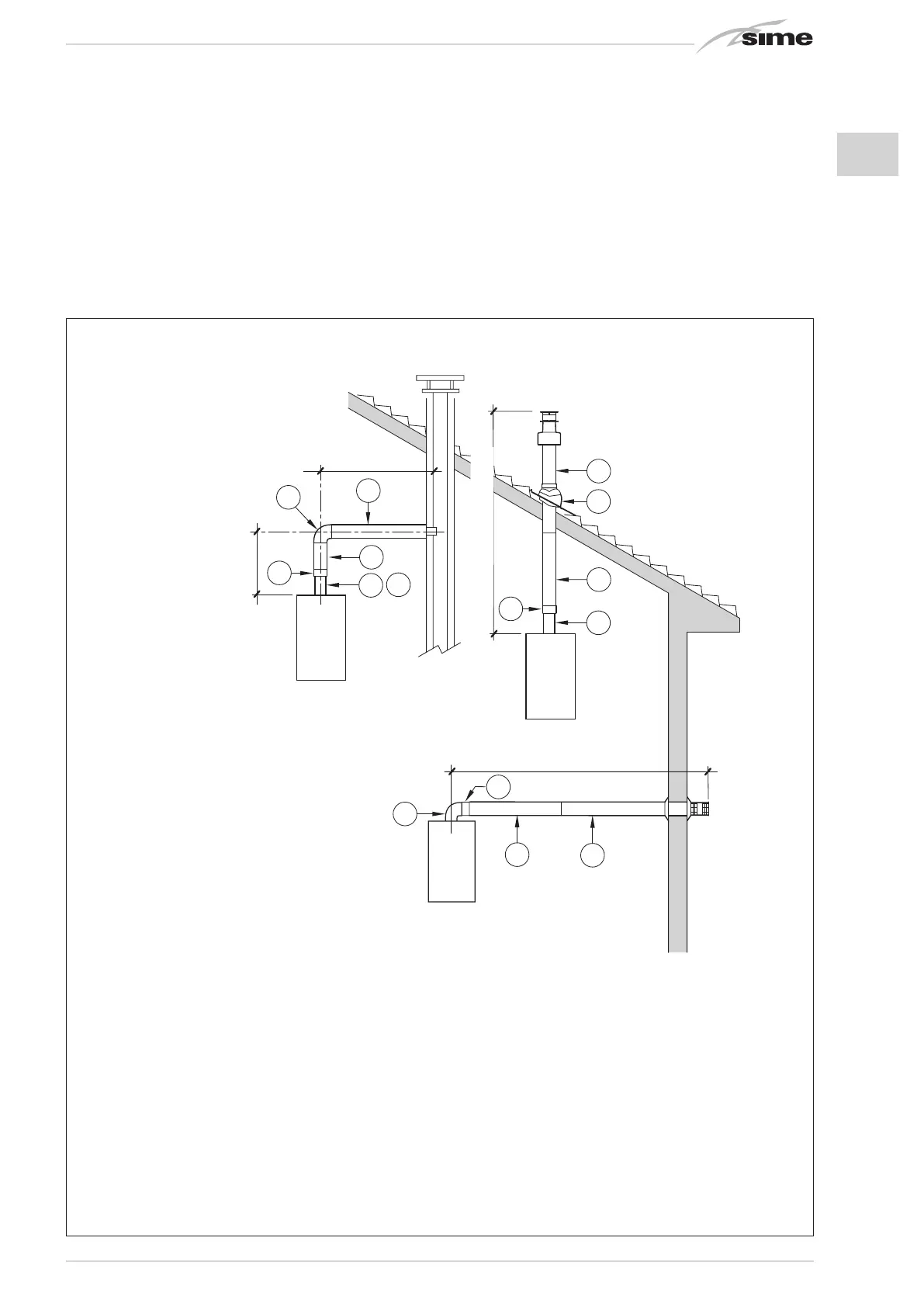
The diagrams in fig. 6 show some examples
of the different types of ø 80/125 coaxial
discharge modalities.
2.8 INSTALLATION OF SEPARATE
DUCTS (versions “BF - BFT”)
(fig. 7)
When installing, the provisions of the laws in
force must be adhered to, as well as certain
practical suggestions:
– With aspiration directly from outside,
when the duct is longer than 1 metre, it
is advisable to insulate the said duct in
order to avoid the formation of dew on
the outside of the pipe when the weather
is particularly cold.
– With ducts with discharge positioned out-
side the building, or in cold environments,
insulation is necessary to avoid difficulty
in starting the burner. In these cases, a
condensation system on the pipes must
be provided for.
C12
C32
C42
2
7
6
4
1
2
min. 4 m - max 7 m
8
x
y
x + y = min. 3,5 m/max 6 m "25"
x + y = min. 3,0 m/max 6 m "30-35-40"
5
5
3
8
2
1
1
min. 3,5 m - max 6 m "25"
min. 3,0 m - max 6 m "30-35-40"
2
Fig. 6
KEY
1 Coaxial duct kit code 8084830
2 Extension L. 1000 code 8096130
3 Vertical extension L. 200 with coupling code 8086908
4a Additional 90° elbow code 8095820
4b Additional 45° elbow code 8095920
5 Adapter for 80/125 code 8095920
6 Tile for joint code 8093120
7 Terminal for roof exit L. 1284 code 8091200
8 Vertical condensation collector L. 200 code 8092803
IMPORTANT:
– Each additional 90° elbow installed reduces the available length by 1.0 metres.
– Each additional 45° elbow installed reduces the available length by 0.80 metres.
– The insertion of the condensation collector (8) is obligatory in C32 discharge type.
– The insertion of the condensation collector (8) is obligatory in C42 discharge type when
the stretch “y” is longer than 1.3 metres.