48
– If the pipe passes through inflammable
walls, insulate the stretch of the fumes
discharge pipe that passes through the
wall with rounded glass wool 30 mm thick
and with a density of 50 kg/m
2
.
The maximum total length, which is the
sum of lengths of the aspiration and
discharge pipes, is determined by the loss
of charge of the single accessories inser-
ted and must not result as more than 7.0
mm H2O in version “20” - 7.6 mm H2O in
version “25” - 9 mm H2O in version “30” -
12 mm H2O in version “35”.
For the loss of charge of the accessories,
refer to Table 1 and to the example given
in fig. 7.
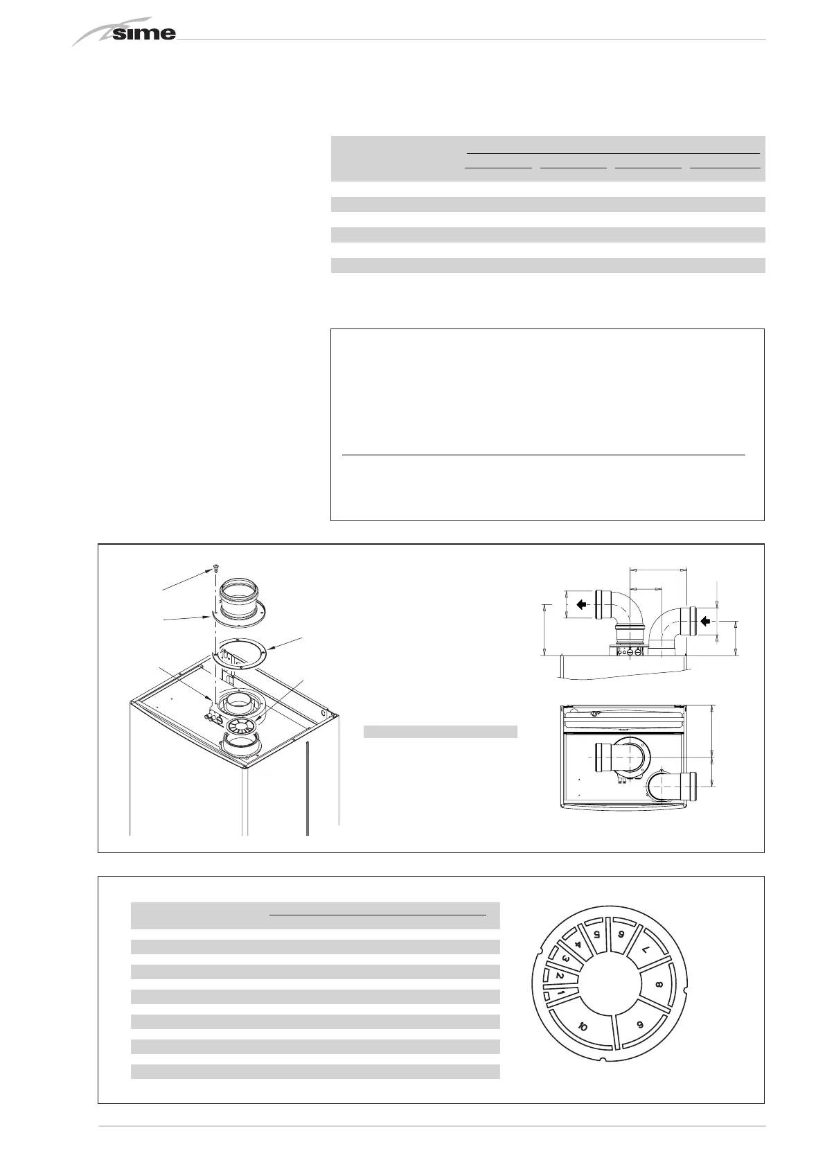
2.8.1 Separate ducts kit
(fig. 8 - fig. 8/a - fig. 9)
The separate ducts kit code 8089904 (fig.
8) is supplied with the aspiration diaphragm
which must be used, according to the maxi-
mum loss of charge allowed in both the
ducts, as indicated in fig. 8/a.
To use the air intake vent in this type of
discharge, the following operations must be
carried out (fig. 9):
Example of allowable installation “25 BF” calculation in that the sum of the head losses of the
single fittings is less than 7.6 mm H
2
O:
Intake Outlet
7 meter horizontal pipe ø 80 x 0.20 1.40 –
7 meter horizontal pipe ø 80 x 0.30 – 2.10
No. 2 90° elbows ø 80 x 0.35 0.70 –
No. 2 90° elbows ø 80 x 0.40 – 0.80
No. 1 wall terminal ø 80 0.15 0.50
Total head loss 2.25 + 3.40 = 5.65 mmH
2
O
With this total head loss, remove the segments from No. 1 to No. 7 from diaphragm in the intake
pipe.
1
2
3
4
6
165
110
165
K
ø 80
ø 80
100
92
Fig. 8
Fig. 8/a
Fig. 7
KEY
1 ø 125/95 sponge seal
2 Fixing screw
3 Flue outlet flange
4 Inlet air diaphragm
6 Manifold with intakes
20 25 30 35
K mm 180 180 205 205
No. segments
Total load loss
mm H2O
to remove
20 25 30 35
none 0 ÷ 2.0 0 ÷ 0.8 - -
No. 1 2.0 ÷ 3.0 0.8 ÷ 1.6 - -
No. 1 e 2 3.0 ÷ 4.0 1.6 ÷ 2.4 0 ÷ 1.0 0 ÷ 1.0
from No. 1 to 3 4.0 ÷ 5.0 2.4 ÷ 3.1 1.0 ÷ 2.0 1.0 ÷ 2.0
from No. 1 to 4 5.0 ÷ 6.0 3.1 ÷ 3.8 2.0 ÷ 3.0 2.0 ÷ 3.0
from No. 1 to 5 6.0 ÷ 7.0 3.8 ÷ 4.5 3.0 ÷ 4.0 3.0 ÷ 4.0
from No. 1 to 6 --- 4.5 ÷ 5.2 4.0 ÷ 4.8 4.0 ÷ 5.0
from No. 1 to 7 --- 5.2 ÷ 5.8 4.8 ÷ 5.6 5.0 ÷ 6.0
from No. 1 to 8 --- 5.8 ÷ 6.4 5.6 ÷ 6.4 6.0 ÷ 7.0
from No. 1 to 9 --- 6.4 ÷ 7.0 6.4 ÷ 7.2 7.0 ÷ 8.0
from No. 1 to 10 --- - 7.2 ÷ 8.0 8.0 ÷ 10.0
without diaphragm
--- 7.0 ÷ 7.6 8.0 ÷ 9.0 10.0 ÷ 12.0
TABLE 1
Accessories ø 80 Load loss (
mmH2O)
20 25 30 35
Intake
Outlet
Intake
Outlet
Intake
Outlet
Intake
Outlet
90° elbow MF 0.30 0.35 0.35 0.40 0.45 0.50 0.65 0.70
45° elbow MF 0.25 0.30 0.30 0.35 0.40 0.45 0.60 0.65
Extension L. 1000 (horizontal) 0.15 0.25 0.20 0.30 0.25 0.35 0.30 0.40
Extension L. 1000 (vertical) 0.15 0.05 0.20 0.10 0.25 0.15 0.30 0.20
Wall terminal 0.10 0.40 0.15 0.50 0.20 0.80 0.20 1.20
T-shaped condensation collector --- 0.70 --- 0.80 --- 1.00 --- 1.40
Roof exit terminal* 1.30 0.05 1.60 0.10 2.00 0.20 2.50 0.30
* The loss of the roof exit terminal in aspiration concludes the collector code 8091400
 Loading...


