49
EN
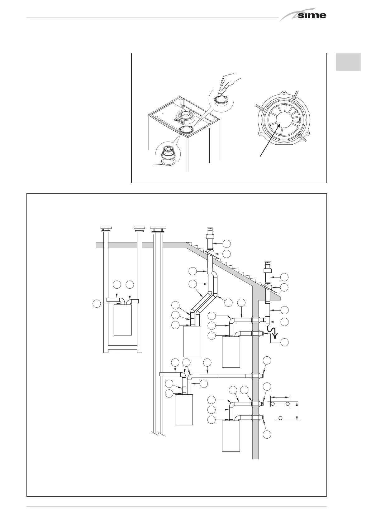
– Remove the base of the air intake vent by
cutting it with a tool (a);
– Turn the air intake vent upside down and
replace the gasket (5) with that supplied
in the kit code 8089904;
– Insert the aspiration diaphragm supplied
in the kit code 8089904, pushing it home;
– Only for versions “20 BFT” fit onto the
diaphragm the plastic reducer supplied
together with the boiler.
Now the extension or the curve can be fitted
into the special seat in order to complete
the aspiration pipe (no washer or sealant
is necessary).
2.8.2 Outlet systems (fig. 9/a)
The diagrams in fig. 9/a illustrate a number
of examples of different types of separate
outlets.
max 0,5 m
max 0,5 m
C12
B52
1
4
9
C52
B52
C32
C42
3
2
11
10
C82
B22
6
5
6
12
3
11
10
3
7
1
8
3
1
3
2
3
3 2
1
3
2
3
6
3
1
8 3
KEY
1 Separate flue kit code 8089904
2a
90° elbow MF (n° 6) code 8077410
2b
90° elbow MF with intake code 8077407
2c
Isolated 90° elbows MF code 8077408
3a
Extension L. 1000 (n° 6) code 8077309
3b Insulated e
xtension L. 1000 code 8077306
3c
Extension L. 500 (n° 6) code 8077308
3d
Extension L. 135 code 8077304
4
Outlet terminal code 8089501
5 Int.-est. ring kit code 8091500
6
Intake terminal code 8089500
7
45° elbow MF (n° 6) code 8077411
8
Condensation outlet L. 135 code 8092800
9 Doubler fitting code 8091400
10 Tile with articulated joint code 8091300
11 Roof outlet terminal L. 1390 code 8091201
12 Tee condensation outlet code 8093300
a
b
5
Fig. 9/a
IMPORTANT: In type C52 the outlet and inlet flues must not come out on opposite walls.
ATTENTION: The three seats forese-
en on the diaphragm allow for fitting
the air intake vent in only one posi-
tion (the enumeration of the sectors
faces inwards).
Fig. 9
CONFIGURATION C62: discharge and aspiration is by means of pipes available on sale and certified separately (the pressure loss in the
ducts must be calculated according to the Standard UNI EN 13394)
In vers. “20 BFT” fit the plastic
reducer supplied with the boiler in
the position indicated.