50
2.9 FORCED EXHAUST
TYPE B22P - B52P (fig. 10)
Comply with the following requirements
during installation:
– Insulate the exhaust pipe and install a
condensation collection system at the
base of the vertical pipe.
– If the pipe passes through combustible
walls, insulate the section of the flue pipe
passing through the wall with a 30 mm
thick fibreglass pipe covering with a den-
sity of 50 kg/m
3
.
In “BF - BFT” models this type of exhaust
pipe is installed using the special kit, code
8089904. For kit assembly instructions,
refer to point 2.8.1. Protect the intake with
the optional accessory, code 8089501.
The accessory is assembled by cutting
a 50 mm long segment from an ordi-
nary ø 80 extension and inserting it on
the air intake, on which the accessory is
then fitted, anchored to the pipe segment
with the screws provided (fig. 10). Kit
code 8089904 is supplied with the intake
diaphragm, which must be used as shown in
fig. 8/a, depending on the maximum permit-
ted flow. Maximum flow resistance must
be no more than 7,0 mm H2O in vers. “20”
- 7,6 mm H2O in model “25” - 9 mm H2O
in model “30” - 12 mm H2O in model “35”.
As the maximum pipe length is determi-
ned by adding up the flow resistance of
the various individual accessories installed,
refer to Table 1 for calculation.
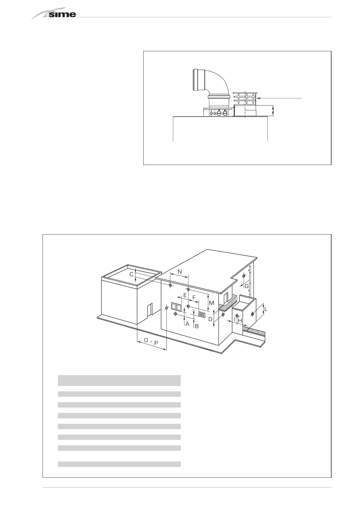
2.10 POSITIONING OF OUTLET
TERMINALS (fig. 11)
The outlet terminals for forced draught
systems may be located on the outer walls
of the building Table 2 shows approximate,
non-binding minimum distances to be met
for a building of the type shown in fig. 11.
1)
Terminals below a practicable balcony must be located in such
a way that the total path of the smoke from its outlet point from
the terminal to its outlet point from the external perimeter of the
balcony, including the height of possible railings, is not less than
2000 mm.
2) When siting terminals, where materials that may be subject
to the action of the combustion products are present in the
vicinity, e.g., eaves, gutters and downspouts painted or made
of plastic material, projecting timberwork, etc., distances of
not less than 1500 mm must be adopted, unless adequate
shielding is provided to guard these materials.
Fig. 11
50
cod. 8089501
Fig. 10
TABLE 2
Siting of terminal Appliances from 7 to 35 kW
(distances in mm)
A - below openable window 600
B - below ventilation opening 600
C - below eaves 300
D - below balcony (1) 300
E - from adjacent window 400
F - from adjacent ventilation opening 600
G - from horizontal or vertical soil or drain pipes (2) 300
H - from corner of building 300
I - from recess in building 300
L - from ground level or other treadable surface 2500
M - between two terminals set vertically 1500
N - between two terminals set horizontally 1000
O - from a surface facing without
openings or terminals 2000
P - as above but with openings and terminals 3000