51
EN
2.11 ELECTRICAL WIRING
If you must replace the electric power cable
supplied with the boiler, order it exclusively
from Sime. The power supply must be
single-phase 230V - 50 Hz through a main
switch protected by a fuse with a distance of
at least 3 mm between contacts.
The boiler must be connected with an effi-
cient grounding system. SIME shall not be
held liable for injury or damage resulting
from failure to ground the boiler.
ATTENTION: Before every intervention on
the boiler, cut off the electricity supply by
means of the main switch of the system,
since even if the boiler is “OFF”, the elec-
trical panel remains connected to the
electricity.
2.11.1 Chronothermostat connection
Connect the chronothermostat as indica-
ted in the boiler electrical diagram (see
paragraph 2.12) after having removed the
existing bridge.
The chronothermostat to be used must be
of a class conforming to the standard EN
607301 (clean electrical contact).
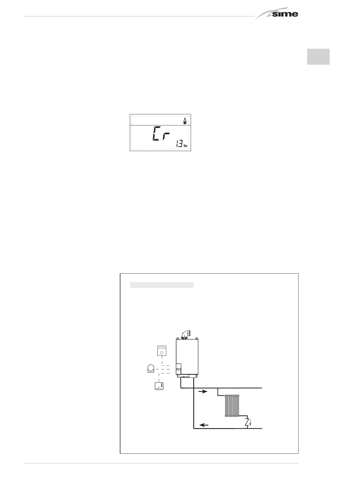
2.11.3 Remote control SIME HOME
connection (optional)
The boiler is designed for connection to a
remote control unit, supplied on request
(code 8092280/81).
The remote control unit SIME HOME allows
for complete remote control of the boiler.
The boiler display will show the following
message:
For installation and use of the remote con-
trol, follow the instructions in the package.
NOTE: Ensure PAR 10 set to 1
(PAR 10 = 1).
2.11.4 External sensor connection
The boiler is designed for connection to an
external temperature sensor, supplied on
request (code 8094101), which can auto-
matically regulate the temperature value of
the boiler output according to the external
temperature.
For installation, follow the instruction in the
package.
For installation, follow the instruction in the
package.
It is possible to make corrections
to the values read by the drill acting on the
PAR 11.
2.11.5 D.H.W. sensor connection in vers.
“20-25 BFT”
The “20-25 BFT” version is provided with
D.H.W. sensor (SB) linked to the connector
CN5. When the boiler is coupled to D.H.W.
storage tank, introduce the sensor into the
special sleeve in the D.H.W. storage tank.
ATTENTION: The “BFT” version is designed
for connection to D.H.W. storage tank, for
use ONLY FOR HEATING it is necessary:
- to disconnect the D.H.W. sensor (SB);
- set PAR 2=4.
All modules are designed to be used by
qualified technical personnel.
1. Visualizzazione temperatura esterna
solo con sonda esterna collegata
2. Visualizzazione temperatura sonda
riscaldamento (SM)
3. Visualizzazione temperatura sonda
sanitario (SS) solo per caldaie istantanee
4. Visualizzazione temperatura sonda
ausiliaria o sonda bollitore (SB)
6. Visualizzazione temperatura
riscaldamento riferita al primo circuito
7. Visualizzazione temperatura
riscaldamento riferita al secondo circuito
13. Visualizzazione codice errore
penultima anomalia
14. Visualizzazione numero totale
delle anomalie
10. Visualizzazione ore di funzionamento del bruciatore in h x 100 (es. 14.000 e 10)
11. Visualizzazione numero di accensioni del bruciatore x 1.000 (es. 97.000 e 500)
12. Visualizzazione codice errore
ultima anomalia
15. Contatore accessi parametri
installatore (es. 140 accessi)
5. Visualizzazione temperatura sonda
fumi
8. Visualizzazione corrente
di ionizzazione in µA
16. Contatore accessi parametri
OEM (es. 48 accessi)
9. Visualizzazione corrente al
modulatore in mA
2.11.6 Use with different
electronic systems
Some examples are given below of boiler
systems combined with different electronic
systems. Where necessary, the parame-
ters to be set in the boiler are given. The
electrical connections to the boiler refer
to the wording on the diagrams (figs. 13 -
13/a - 13/b).
The zone valve control starts at every
demand for heating of the zone 1 (it is from
part of the TA1 or the CR).
Description of the letters indicating the
components shown on the system dia-
grams from 1 to 14:
M System output
R System return
CR Remote control SIME HOME
SE External temperature sensor
TA 1-2-3-4 Zone room thermostat
CT 1-2 Zone c
hronothermostat
VZ 1-2 Zone valve
RL 1-2-3-4 Zone relay
Sl Hydraulic separator
P 1-2-3-4 Zone pump
SB D.H.W. sensor
PB D.H.W. pump
IP Floor system
EXP Expansion card ZONA MIX (code
8092234)/INSOL (code 8092235)
VM Three-way mixer valve
RM
SE
TA3
TA1
SE
SI
RL3
P3
P2
TA2
IP
EXP
VM
EXP
IP
P4
TA4
RL4
TA1
TA2
SI
RM
SE
TA1
TA2
TA2
SE
TA
P2
RL
RL1
RL2
P1
P
CR
CR
RM
SE
CT2
TA1
SE
CT1
TA2
VZ1
VZ2
ZONA
GIORNO
(70¡C)
ZONA
NOTTE
(50¡C)
RM
SE
CT2
TA1
SE
CT1
SI
RL2
P2
P1
TA2
RL1
ZONA
GIORNO
(70¡C)
ZONA
NOTTE
(50¡C)
RM
SE
TA2
TA1
SE
TA1
SI
RL2
P2
P1
TA2
CR
CR
EXP
VM
EXP
RM
SE
TA2
TA1
SE
TA1
SI
RL2
P2
P1
PB
RL1
BOLLITORE
PB
SB
SB
IP
RM
SE
TA1
TA2
TA1
SE
TA
P2
RL
SI
RL1
RL2
P1
P
TA2
SE
RM
SE
VZ
VZ1
TA2
VZ2
CR
CR
VZ1
TA1
TA2
SE
RM
SE
TA
VZ
TA1
VZ1
TA2
VZ2
CR
CR
TA1
SE
RM
SE
TA
VZ
TA1
VZ1
TA2
VZ2
R
M
SE
TA
CR
TA1
CR
SE
R
M
SE
CR
CR
SE
SB
M2
R2
SB
BOLLITORE
S1
SB
S2
R
M
SE
TA1
SE
SI
P1
TA2
EXP
VM
EXP
IP
TA1
TA2
P2
VM
IP
EXP
EXP (INSOL)
Vers. BFT / T
RM
SE
TA1
SE
SI
P1
TA2
EXP
VM
EXP
IP
TA1
TA2
P2
VM
IP
EXP
1 BASIC SYSTEM
SYSTEM WITH A DIRECT ZONE AND ROOM THERMOSTAT, OR
WITH REMOTE CONTROL SIME HOME (Code 8092280/81)
AND EXTERNAL SENSOR (Code 8094101)

 Loading...


