61
EN
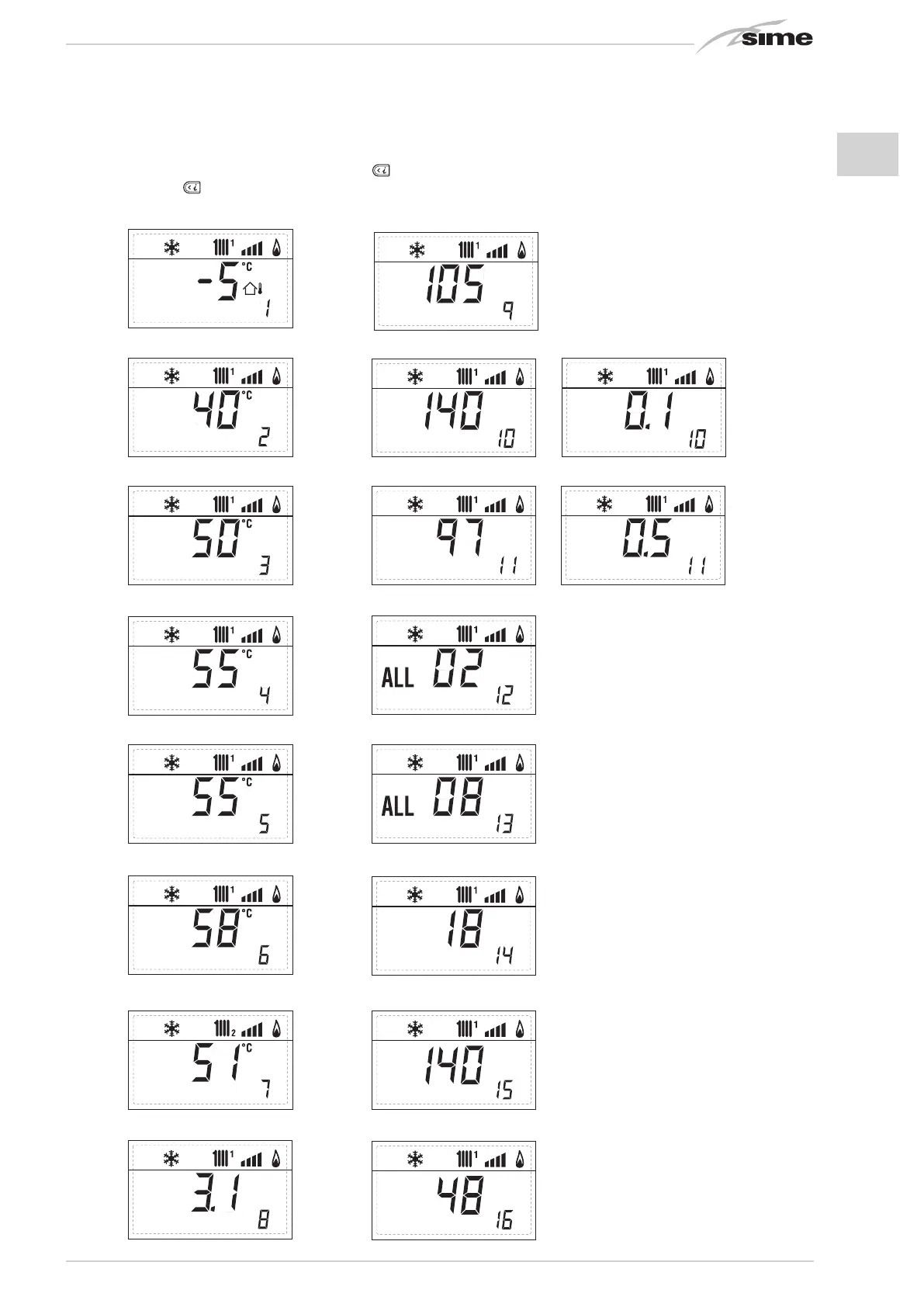
3.2 ACCESS TO INSTALLER’S INFORMATION
For access to information for the installer, press the key
(3 fig. 14). Every time the key is pressed, the display moves to the next item of
information. If the key
is not pressed, the system automatically quits the function. List of information:
1. Visualizzazione temperatura esterna
solo con sonda esterna collegata
2. Visualizzazione temperatura sonda
riscaldamento (SM)
3. Visualizzazione temperatura sonda
sanitario (SS) solo per caldaie istantanee
4. Visualizzazione temperatura sonda
ausiliaria o sonda bollitore (SB)
6. Visualizzazione temperatura
riscaldamento riferita al primo circuito
7. Visualizzazione temperatura
riscaldamento riferita al secondo circuito
13. Visualizzazione codice errore
penultima anomalia
14. Visualizzazione numero totale
delle anomalie
10. Visualizzazione ore di funzionamento del bruciator
e in h x 100 (es. 14.000 e 10)
11. Visualizzazione numero di accensioni del bruciator
e x 1.000 (es. 97.000 e 500)
12. Visualizzazione codice errore
ultima anomalia
15. Contatore accessi parametri
installatore (es. 140 accessi)
5. Visualizzazione temperatura sonda
fumi
8. Visualizzazione corrente
di ionizzazione in µA
16. Contatore accessi parametri
OEM (es. 48 accessi)
9. Visualizzazione corrente al
modulatore in mA
1. Visualisation of external temperature,
only with external sensor connected
2. Visualisation of heating
temperature sensor (SM)
3. Visualisation of D.H.W.
temperature sensor (SS)
4. Visualisation of auxiliary
temperature sensor
6. Visualisation of heating temperature
of first circuit
7. Visualisation of heating temperature
of second circuit
8. Visualisation of ionisation
current in µA
10. Visualisation of hours of functioning of the burner in h x 100 (e.g. 14000 and 10)
11. Visualisation of number of times the burner has ignited x 1000 (e.g. 97000 and 500)
12. Visualisation of error code
of last anomaly
14. Visualisation of total number
of anomalies
5. Visualisation of smoke
temperature sensor
13. Visualisation of error code
of penultimate anomaly
15. Parameter access counter– Installer
(i.e. 140 accesses)
16. Parameter access counter–OEM (i.e.
48 accesses)
9. Visualisation current to the modulator
in mA