63
EN
3.3 ACCESS TO INSTALLER’S
PARAMETERS
For access to the installer’s parameters,
press simultaneously the keys
and
for 5 seconds (3 fig. 14).
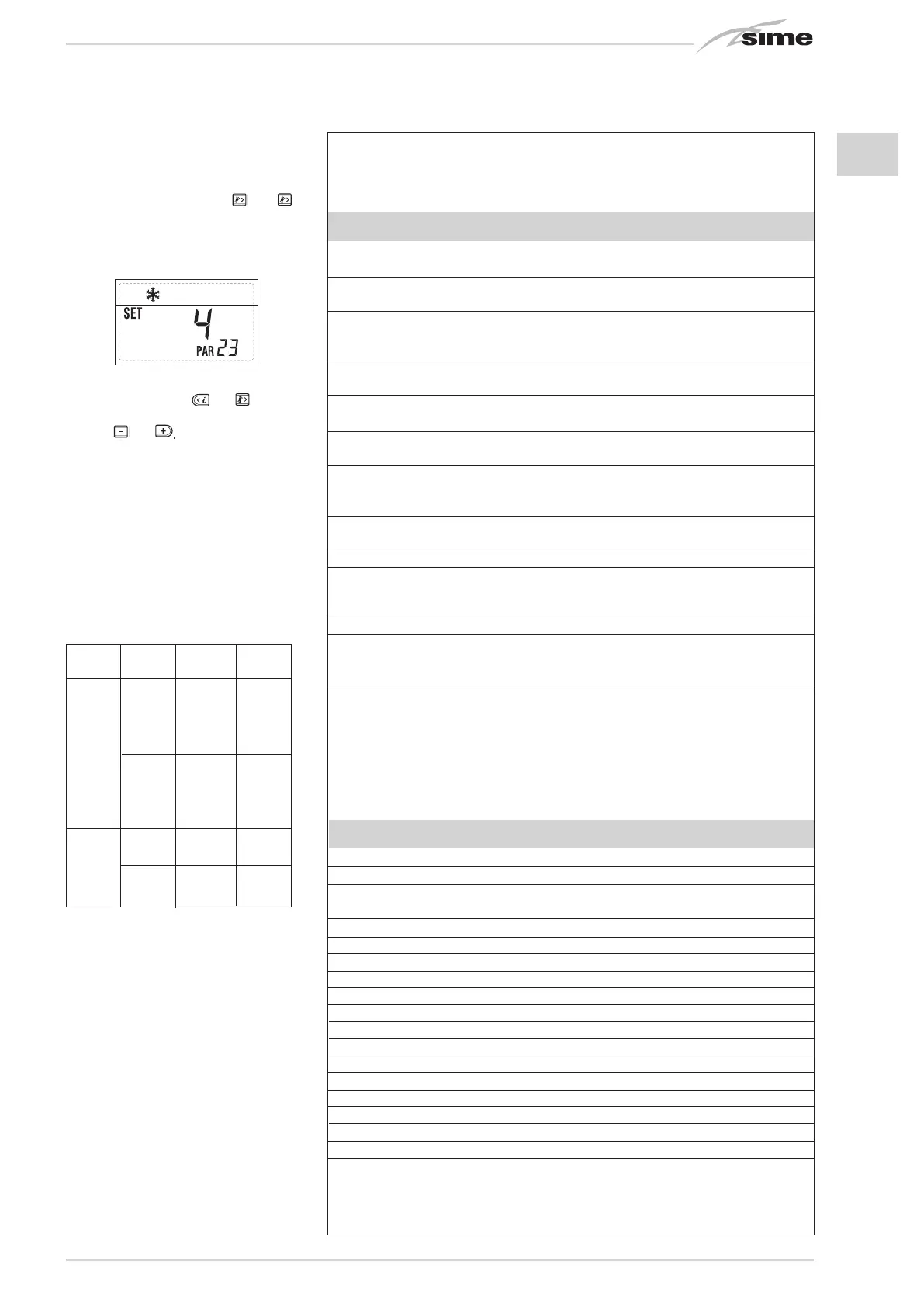
For example, the parameter PAR 23 is
visualised on the display of the control panel
in the following way:
The parameters scroll forwards and
backwards with the key
and
and the
default parameters can be changed with
the keys
and
.
The standard visualisation returns automa-
tically after 60 seconds, or by pressing one
of the control keys (2 fig. 14).
3.3.1 Replacing the board or
RESETTING parameters
If the electronic board is replaced or reset,
it is necessary to configure PAR 1 and PAR
2 by associating the following values to each
type of boiler to be able to restart the boiler:
1. Visualizzazione temperatura esterna
solo con sonda esterna collegata
2. Visualizzazione temperatura sonda
riscaldamento (SM)
3. Visualizzazione temperatura sonda
sanitario (SS) solo per caldaie istantanee
4. Visualizzazione temperatura sonda
ausiliaria o sonda bollitore (SB)
6. Visualizzazione temperatura
riscaldamento riferita al primo circuito
7. Visualizzazione temperatura
riscaldamento riferita al secondo circuito
13. Visualizzazione codice errore
penultima anomalia
14. Visualizzazione numero totale
delle anomalie
10. Visualizzazione ore di funzionamento del bruciatore in h x 100 (es. 14.000 e 10)
11. Visualizzazione numero di accensioni del bruciatore x 1.000 (es. 97.000 e 500)
12. Visualizzazione codice errore
ultima anomalia
15. Contatore accessi parametri
installatore (es. 140 accessi)
5. Visualizzazione temperatura sonda
fumi
8. Visualizzazione corrente
di ionizzazione in µA
16. Contatore accessi parametri
OEM (es. 48 accessi)
9. Visualizzazione corrente al
modulatore in mA
BOILER GAS MODELS PAR 1
METHANE 20 1
25 2
30 3
BF/BFT 35 4
LPG 20 5
25 6
30 7
35 8
METHANE 25 9
OF 30 10
LPG 25 11
30 12
PARAMETERS INSTALLER
FAST CONFIGURATION
PAR DESCRIPTION RANGE UNIT OF INC/DEC DEFAULT
MEASUREMENT UNIT SETTING
1 Combustion configuration -- = ND = = “--”
1 ... 12
2 Hydraulic configuration -- = ND = = “--”
1 ... 14
1 =
DHW + Recirc. pump
3 Timetable 2 programmer 2 = DHW = = 1
3 = Recirculation pump
4 Pressure transducer disabler 0 = Disabled = = 1
1 = Enabled
5 Assignment of auxiliary relay AUX 1 = Remote supply = = 1
(D.H.W. tank) 2 = Recirculation pump
6 Luminous bar indicating presence 0 = Disabled = = 1
of voltage 1 = Enabled
0 = Not assigned
7 Allocation of SIME HOME channels 1 = Circuit 1 = = 1
2 = Circuits 1 and 2
8 - - - - -
9 - - - - -
1 = SIME HOME
10 Remote control option setting 2 = CR 53 = = 1
3 = RVS
11 Correction values external sensor -5 ... +5 °C 1 0
-- = Always
12 Backlighting duration 0 = Never sec. x 10 1 3
1 ... 199
0 = Minimum
13 Modulating pump speed 1 = Maximum = = 1
2 = Automatic
D.H.W. - HEATING
PAR DESCRIPTION RANGE UNIT OF INC/DEC DEFAULT
MEASUREMENT UNIT SETTING
20 D.H.W. minimum temperature 10 °C ... PAR 21 °C 1 30
21 D.H.W. maximum temperature PAR 20 ... PAR 62 OEM °C 1 60
22 Anti-legionella (only D.H.W. tank) 0 = Disabled = = 0
1 = Enabled
23 Boiler antifreeze 0 ... +20 °C 1 3
24 External sensor antifreeze - 15 ... +5 °C 1 - 2
25 Climatic curve setting Zone 1 3 ... 40 = 1 20
26 Climatic curve setting Zone 2 3 ... 40 = 1 20
27 Minimum temperature Zone 1 PAR 64 OEM ... PAR 28 °C 1 20
28 Minimum temperature Zone 1 PAR 27 ... PAR 65 OEM °C 1 80
29 Minimum temperature Zone 2 PAR 64 OEM ... PAR 30 °C 1 20
30 Maximum temperature Zone 2 PAR 29 ... PAR 65 OEM °C 1 80
31 Maximum heating power 30 ... 100 % 1 100
32 C.H. post-circulation time 0 ... 199 Sec. 10 30
33 Pump activation delay Zone 1 0 ... 199 10 sec. 1 1
34 Re-ignition delay 0 ... 10 Min. 1 3
35 Integrative sources activation threshold -- , 15 ... 80 °C 1 “--”
36 D.H.W. post-circulation time 0 ... 199 Sec. 1 0
39 Saturation zone modulation -- = Enabled % 1 100
D.H.W. flowmeter 0 ... 100

 Loading...


