66
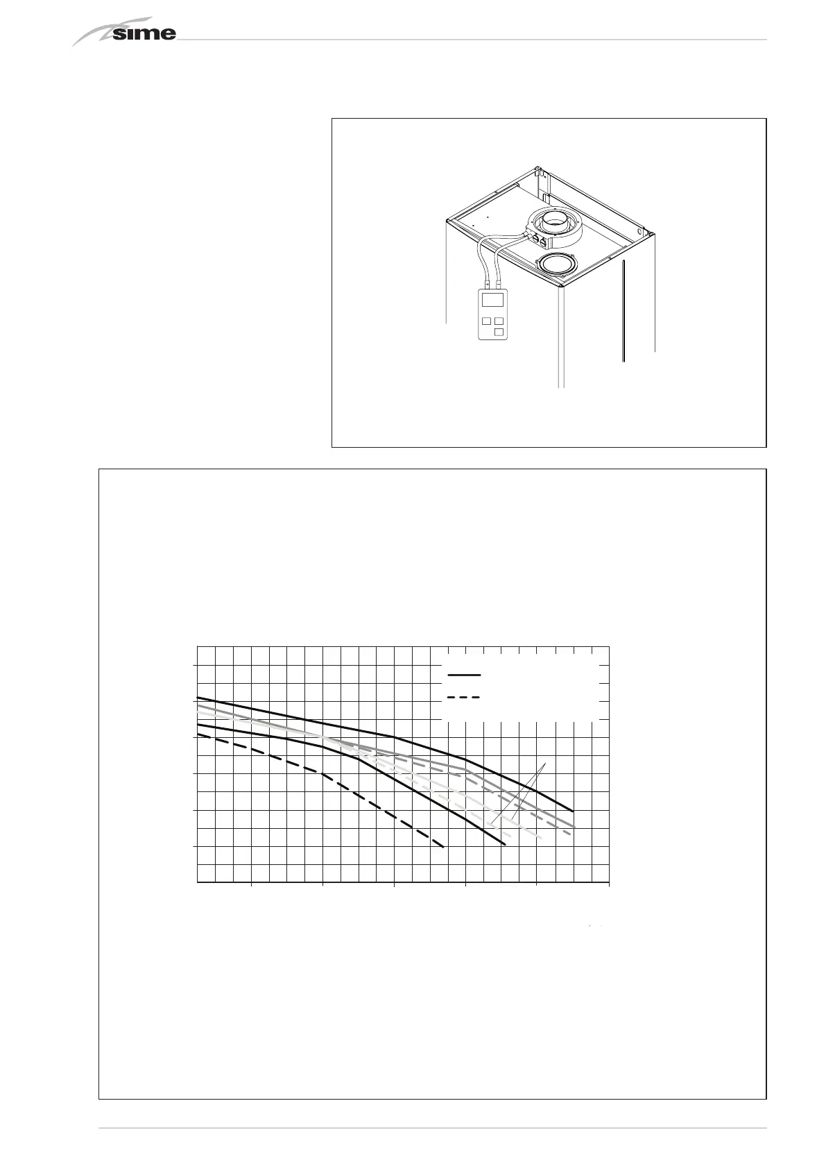
3.9 FUMES PRESSURE SWITCH
vers. BF-BFT (fig. 16)
The pressure switch is calibrated by the
manufacturer at the following values:
5.3 - 6.3 H2O for vers. “25 BF - 25 BFT”
3.6 - 4.6 H2O for vers. “30 BF”
4.6 - 5.6 H2O for vers. “20 BF - 35 BFT”
which can guarantee boiler functioning also
with aspiration and discharge pipes of the
maximum length allowed.
The value of the signal to the pressure
switch is measured by a differential pressu-
re gauge connected as indicated in fig. 16.
3.10 HEAD AVAILABLE TO SYSTEM
(fig. 17)
Residual head for the heating system is
shown as a function of rate of flow in the
graph in fig. 17. The speed of the modu-
lating pump is set as default (installation
parameter PAR 13=1).
Fig. 16
0
600
200 12001000800600400
PORTATA (l/h)
PREVALENZA RESIDUA (mbar)
500
400
100
200
300
Murelle EV
25-30 OF
velocitˆ max pompa
velocitˆ min. pompa
20 BFT
25 BF/BFT/GG MT 25 PLUS
25 BF/BFT/GG MT 25 PLUS
30-35 BF/35 BFT /GG MT 30-35 PLUS
25-30 OF
Fig. 17
RESIDUAL HEAD (mbar)
FLOW RATE (l/h)