67
EN
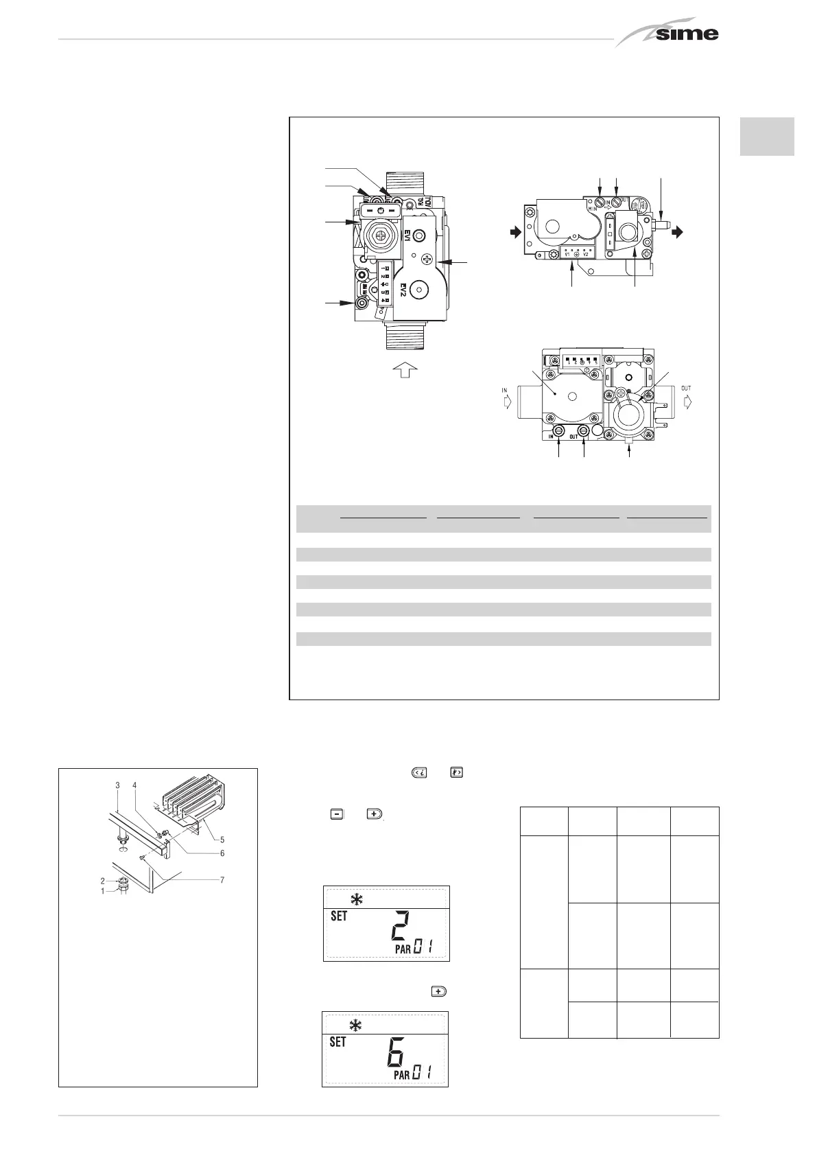
4.1 GAS VALVE (fig. 18)
The boilers are equipped standard with the
SIT 845 SIMGA / HONEYWELL VK 4105M
/ SIEMENS VGU 56 gas valve (fig. 18).
The gas valve is set at two pressure values:
maximum and minimum. According to the
type of gas burnt, these correspond to the
values given in Table 4. The gas pressures
at the maximum and minimum values, are
factory set. Consequently they must not be
altered. Only when you switch the appliance
from one type of gas supply (methane) to
another (butane or propane), it is permitted
to alter the operating pressure.
4.2 GAS CONVERSION (fig. 19)
This operation must be performed by
authorised personnel using original Sime
components.
To convert from natural gas to LPG or vice versa,
perform the following operations (fig. 19):
– Close the gas cock.
– Disassemble the burner manifold (3).
– Replace the main nozzles (6) supplied in a
kit, inserting the copper washer (4). Use
a ø 7 spanner to perform this operation.
– Configure the new fuel as indicated in
point 4.2.1
– For calibrating the maximum and mini-
mum gas pressure values, see point
4.2.2.
– After have ultimated the conversion of
the boiler, please stick onto the casing
panel the plate showing the relevant fee-
ding gas which is included into the kit.
NOTE: When reassembling components
which you have removed, replace gas
seals; test all gas connections after
assembly using soapy water or a product
made specifically for the purpose, being
sure not to use open flame.
4.2.1 New fuel configuration
For access to the installer’s parameters,
press simultaneously keys
and
for 5
seconds (3 fig. 14).
The parameters will scroll up and down with
the keys
and
.
The display pane will show the values of the
parameter PAR 1. If, for example, the boiler
in question is a “25 BF” fuelled by methane,
the following setting SET 2 will appear:
To change the fuel to LPG, it is necessary to
set SET 6, by pressing the key
.
The standard display will automatically
return after 10 seconds.
The table below shows the SET settings to
enter when the type of gas fuel is changed.
4 USE AND MAINTENANCE
3
4
2
1
5
6
4
3
5
KEY
1 Modulator
2 EV1-EV2 coils
3 Pressure inlet upstream
4 Pressure inlet downstream
5 VENT pressure test point
1
2
3 4 5
SIEMENS VGU 56
Fig. 19
KEY
1 Swivel connection 1/2”
2 Locknut 1/2”
3 Burner manifold
4 Washer ø 6.1
5 Burners
6 Nozzle M6
7 Screw
WARNING: To ensure a perfect seal,
always use the washer (4) supplied in the
kit when replacing nozzles, even in burner
units for which it is not specified.
Fig. 18
TABLE 4
Model Burner max pressure mbar Modulator current mA Burner min pressure mbar Modulator current mA
G20 (*) G30 G31 G20 (*) G30 G31 G20 (*) G30 G31 G20 (*) G30 G31
25 OF 11.0 27.7 35.7 130 165 165 1.8 4.7 4.7 0 0 0
30 OF 11.1 27.7 35.7 130 165 165 1.9 4.8 4.8 0 0 0
25 BF 11.8 28.5 36.5 130 165 165 2.0 4.8 4.8 0 0 0
30 BF 12.0 28.5 36.5 130 165 165 2.1 5.0 5.0 0 0 0
35 BF 13.7 28.2 36.2 130 165 165 2.2 4.5 4.5 0 0 0
20 BFT 11.0 28.5 36.5 130 165 165 1.9 4.8 4.8 0 0 0
25 BFT 11.8 28.5 36.5 130 165 165 2.0 4.8 4.8 0 0 0
(*) Max. burner pressure is guaranteed only when the supply pressure exceeds the max. burner pressure by at least 3 mbar.
1. Visualizzazione temperatura esterna
solo con sonda esterna collegata
2. Visualizzazione temperatura sonda
riscaldamento (SM)
3. Visualizzazione temperatura sonda
sanitario (SS) solo per caldaie istantanee
4. Visualizzazione temperatura sonda
ausiliaria o sonda bollitore (SB)
6. Visualizzazione temperatura
riscaldamento riferita al primo circuito
7. Visualizzazione temperatura
riscaldamento riferita al secondo circuito
13. Visualizzazione codice errore
penultima anomalia
14. Visualizzazione numero totale
delle anomalie
10. Visualizzazione ore di funzionamento del bruciatore in h x 100 (es. 14.000 e 10)
11. Visualizzazione numero di accensioni del bruciatore x 1.000 (es. 97.000 e 500)
12. Visualizzazione codice errore
ultima anomalia
15. Contatore accessi parametri
installatore (es. 140 accessi)
5. Visualizzazione temperatura sonda
fumi
8. Visualizzazione corrente
di ionizzazione in µA
16. Contatore accessi parametri
OEM (es. 48 accessi)
9. Visualizzazione corrente al
modulatore in mA
BOILER GAS MODELS PAR 1
METHANE 20 1
25 2
30 3
BF/BFT 35 4
LPG 20 5
25 6
30 7
35 8
METHANE 25 9
OF 30 10
LPG 25 11
30 12
SIT 845 SIGMA HONEYWELL VK 4105M

 Loading...


