68
ATTENTION
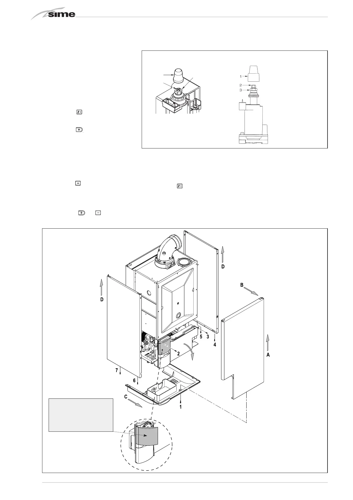
Before removing or refitting the front
panel of the boiler, open the small upper
plastic door.
Code 8112800
Model MURELLE EV 25 BF
Serial n. 9999999999
PAR 1 = 2 (G20) / 6 (G30-G31)
PAR 2 = 5
4.2.2 Adjusting valve pressure (fig. 20)
Set maximum and minimum pressure on
gas valves as follows (fig. 20):
– Connect the column or a manometer to
the intake downstream of the gas valve.
– In “BF/BFT” models, disconnect the
valve VENT pressure test point tube (5
fig. 18).
– Remove the cap (1) from the modulator.
– Press the key
for a few seconds and
completely open the hot sanitary water
faucet.
– Press the key
.
– Remember that rotating clockwise will
increase pressure while rotating anti-
clockwise will diminish it.
– Adjust maximum pressure using the nut
(3) with a wrench to the maximum pres-
sure value indicated in Table 4.
– Adjust the maximum pressure before
adjusting the minimum.
– Press the key
while the sanitary water
tap is on, with the water running.
– Lock the nut (3) in place, turn the screw/
nut (2) to the minimum pressure indica-
ted in Table 4.
– Press the keys
and
while keeping
the hot sanitary
water running all the time, and check that
the maximum and minimum pressures
correspond to the set values; if necessary
correct the regulation.
– Press the key
again to quit the fun-
ction.
– Put the pipe back on the valve VENT pres-
sure test point.
– Remove the manometer, remembering
to tighten the screw for closing the pres-
sure test point.
– Put the plastic cap (1) back on the modu-
lator and seal with a drop of coloured
sealant if necessary.
4.3 DISMANTLING THE CASING (fig. 21)
The casing may be removed completely to
facilitate boiler maintenance, as shown in
fig. 21. Turn the panel control forward for
access to the internal components of the
boiler.
Fig. 20
3
2
1
KEY
1 Plastic tap
2 Minimum pressure adjusting nut
3 Maximum pressure adjusting nut
SIT 845 SIGMA
HONEYWELL VK 4105M - SIEMENS VGU 56
Fig. 21