69
EN
4.4 MAINTENANCE
To guarantee functioning and efficiency of
the appliance, in respect of the legal provi-
sions in force, it must be regularly checked;
the frequency of the checks depends on the
type of appliance and the installation and
usage conditions.
In any case, it should be inspected at least
once a year by a qualified technician.
Carry out the cleaning of the generator in
the following way:
– Turn the main switch off to stop electric
power reaching the boiler and close the
gas feed cock.
– Remove the outer casing and the gas
burner manifold unit. To clean the burner,
blow in a jet of air, so as to remove any
dust particles that may have accumula-
ted.
– Clean the heat exchanger, removing any
dust or residue from combustion. When
cleaning the heat exchanger or the bur-
ners, chemical products or steel brushes
MUST NOT BE USED.
Make sure that the tops of the burners
with the holes are free from encrusta-
tions.
– Reassemble the items removed from the
boiler, making sure to follow the correct
sequence.
– Check operation of the main burner.
– After assembly of all the gas connections,
these must be tested for soundness,
using soapy water or appropriate pro-
ducts. DO NOT USE NAKED FLAMES.
– Do not use calcium chloride to treat
the plastic component during generator
maintenance.
4.4.1 Chimney sweep function (fig. 22)
To check boiler combustion, press the
installer’s key
for a few seconds.
The chimney sweep function will switch on
and will continue for 15 minutes. From that
moment, the boiler will start working in hea-
ting mode at maximum power, with cut off
at 80°C and re-ignition at 70°C.
Before activating the chimney sweep fun-
ction make sure that the radiator valves
or eventual zone valves are open.
The test can also be carried out with the
boiler working in D.H.W. mode.
For this, after activating the chimney sweep
function, open one or more hot water fau-
cets. Under these conditions, the boiler
will function at maximum power with the
D.H.W. kept at between 60°C and 50°C.
During the test, the hot water faucets must
remain open.
If the key
and
are pressed during the
15 minutes of the chimney sweep function,
the boiler will be brought respectively to
maximum and minimum power.
The chimney sweep function will automati-
cally switch off after 15 minutes or when
the key
is pressed again.
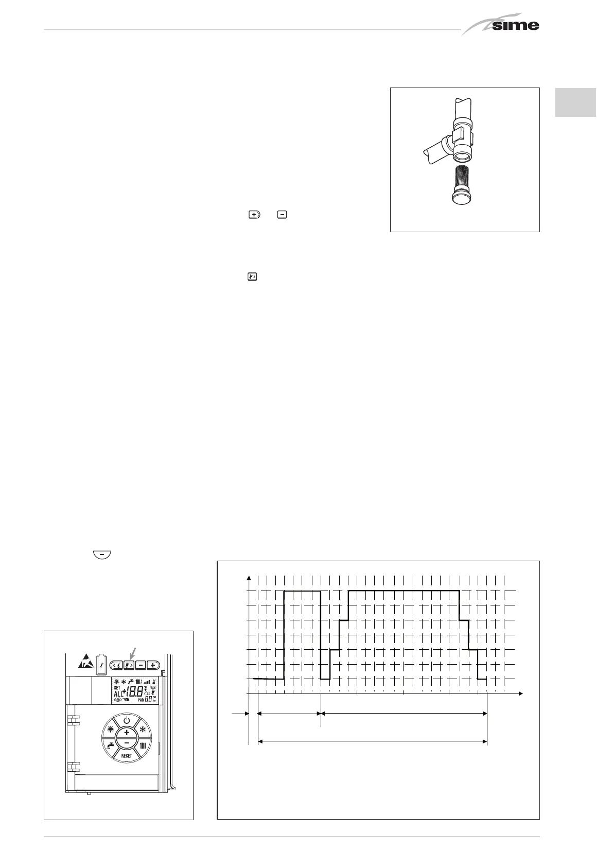
4.4.2 Cleaning the filter “Aqua Guard
Filter System” (fig. 23)
To clean the filter, close the delivery/return
on/off taps, turn off the power to the con-
trol panel, remove the casing and empty the
boiler using the drain provided.
Place a container for collection underneath
the filter, unscrew the cap and proceed to
clean the filter, removing impurities and
limestone deposits.
Check the seal o-ring before reassembling
the cap with the filter.
4.4.3 Operation floor drying (fig. 23/a)
The operation floor drying keeps the floor at
a pre-established temperature profile and
it is activated only for those systems com-
bined with the mixed zone card ZONA MIX
code 8092234. The temperature profiles
can be selected by means of the installer
parameter PAR 43:
0 = Not activated function
1 = Curve setting A
2 = Curve setting B
3 = Curve setting A + B
The turning off of the function happens cli-
cking on the button OFF (return of PAR 43
to the value 0) or automatically at the end
of the function.
The set of the mixed zone follows the deve-
lopment of the selected curve and reaches
a maximum of 55°C. During the function
all the other heating demands are ignored
(heating, sanitary, antifreeze and chimney
sweep).
During the functioning the display shows
the remaining days for the completion of
the function (example mains digits -15 =
15 days lack to the end of the function). The
diagram fig. 23/a reports the development
of the curve.
ATTENTION:
- Observe the relevant standards and
regulations of the floor manufacturer!
- Proper functioning is ensured only
when the plant is correctly installed
(hydraulic system, electrical installa-
tion, settings)! If not observed, the floor
might get damaged!
Fig. 23
Apre
2
2
2
Circuito
riscaldamento 2
Circuito
riscaldamento 3
(impianto tre
zone)
Fig. 22
50
45
40
35
30
20
5101518
[Tag
]
0
25
55
AB
11
57
X
A + B
1 25
[TVw]
Fig. 23/a
TVw Flow temperature setpoint
Tag Period in days
x Start day
A Functional heating
B Floor curing heating

 Loading...


