70
4.5 FUNCTIONING ANOMALIES
When there is a functioning anomaly, an
alarm appears on the display and the blue
luminous bar becomes red.
Descriptions of the anomalies with relative
alarms and solutions are given below:
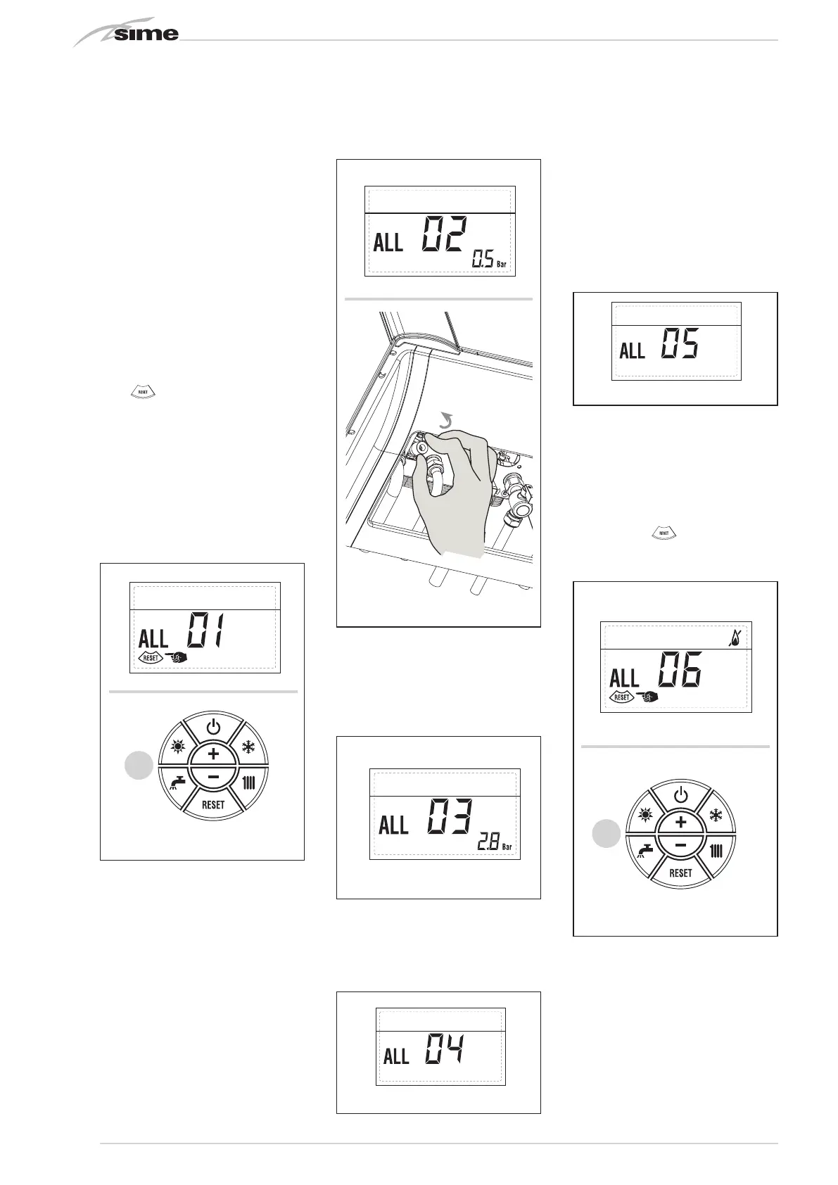
– FUMES DISCHARGE ANOMALY ALARM
01 (fig. 24)
OPEN COMBUSTION CHAMBER
(OF):
The display shows “ALL 01”. The fumes
thermostat has intervened. The boiler
stops for an enforced period of 10 minu-
tes. At the end of this period, the boiler
re-attempts ignition. If the anomaly is
repeated three times in 24 hours, the
symbol RESET starts flashing. Press the
key
of the controls (2) to start up
the boiler again.
SEALED COMBUSTION CHAMBER
(BF/BFT):
The fumes thermostat has intervened. If
the condition causing the problem per-
sists for two minutes, the boiler stops
for an enforced period of thirty minutes.
At the end of this period, the boiler re-
attempts ignition.
– LOW WATER PRESSURE ANOMALY
ALARM 02 (fig. 24/a)
If the pressure detected by the transdu-
cer is lower than 0.5 bar, the boiler stops
and the display shows the alarm “ALL
02”.
Bring the pressure back to normal by ac-
ting on the loading knob. Lower the knob
and turn it anti-clockwise to open until
the pressure indicated by the display is
between 1 and 1.5 bars. WHEN FILLING
HAS BEEN COMPLETED, CLOSE THE
KNOB BY TURNING IT CLOCKWISE.
If the load procedure has to be repeated
several times, it is advisable to check that
the seal of the heating circuit is intact
(check that there are no leaks).
– HIGH WATER PRESSURE ANOMALY
ALARM 03 (fig. 24/b)
If the pressure detected by the transdu-
cer is more than 2.8 bar, the boiler stops
and the display shows anomaly “ALL 03”
– D.H.W. SENSOR ANOMALY ALARM 04
(fig. 24/c)
If the D.H.W. sensor (SS) is open or short
circuited, the boiler will function but will
not modulate the power for sanitary wa-
ter. The display will show the alarm “ALL
04”.
– HEATING SENSOR ANOMALY ALARM
05 (fig. 24/d)
If the heating sensor (SM) is open or
short circuited, the boiler will not function
and the display will show the alarm “ALL
05”.
– FLAME BLOCK ALARM 06 (fig. 24/e)
If the flame control has not detected the
presence of the flame after a complete
ignition sequence, or for any other reason
the card cannot “see” the flame, the boi-
ler will stop and the display will show the
alarm “ALL 06”.
Press the key
of the controls (2) to
start up the boiler again.
– SAFETY THERMOSTAT ANOMALY
ALARM 07 (fig. 24/f)
If the connection with the safety thermo-
stat is interrupted, the boiler will stop; the
flame control will remain waiting to be
switched off for one minute, keeping the
system pump on for that period.
If, the thermostat connection is restored
within the minute, the boiler will start up
working normally again, otherwise it will
Fig. 24/b
Apre
2
2
2
Circuito
riscaldamento 2
Circuito
riscaldamento 3
(impianto tre
zone)
Fig. 24/d
Apre
2
2
2
Circuito
riscaldamento 2
Circuito
riscaldamento 3
(impianto tre
zone)
Apre
2
2
2
Circuito
riscaldamento 2
Circuito
riscaldamento 3
(impianto tre
zone)
Fig. 24/c
Apre
2
2
2
Circuito
riscaldamento 2
Circuito
riscaldamento 3
(impianto tre
zone)
APRE
Fig. 24/a
OPEN
Apre
2
2
2
Circuito
riscaldamento 2
Circuito
riscaldamento 3
(impianto tre
zone)
2
2
Circuito
riscaldamento 2
Circuito
riscaldamento 3
(impianto tre
zone)
Fig. 24/e
Fig. 24
Apre
2
2
2
Circuito
riscaldamento 2
Circuito
riscaldamento 3
(impianto tre
zone)
2
2
Circuito
riscaldamento 2
Circuito
riscaldamento 3
(impianto tre
zone)