71
EN
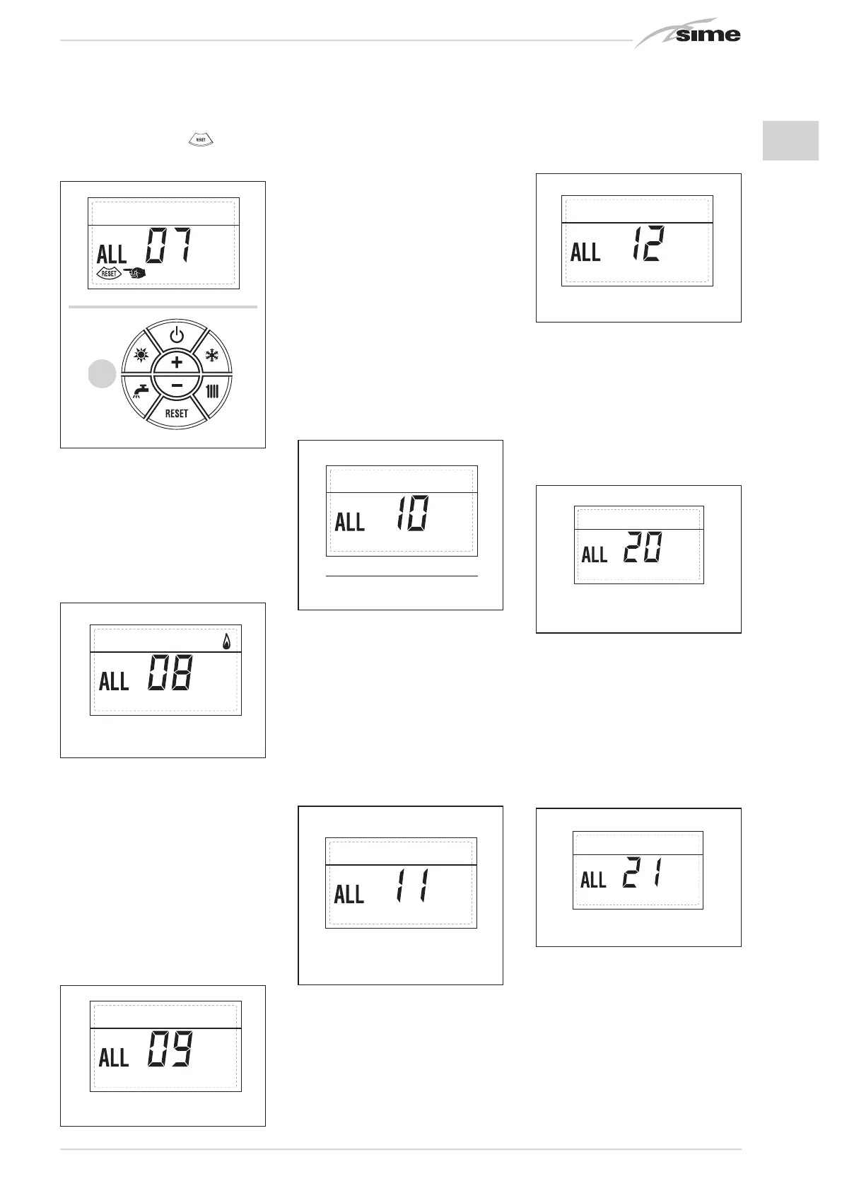
stop and the display will show the alarm
“ALL 07”. Press the key
of the con-
trols (2) to start up the boiler again.
– PARASITE FLAME ANOMALY ALARM
08 (fig. 24/g)
If the flame control section recognises
the presence of flames also in phases
when they should not be present, it me-
ans there is a breakdown in the flame de-
tection circuit; the boiler will stop and the
display will show anomaly “ALL 08”.
– WATER CIRCULATION ANOMALY
ALARM 09 (fig. 24/h)
There is no water circulation in the prima-
ry circuit. If the contacts of the flow gauge
close, the state of anomaly is immediately
quitted.
If the anomalous state persists for one
minute, the boiler is enforcedly stopped
for six minutes. After this time of enfor-
ced inactivity, the boiler will re-attempt
ignition. If the anomaly re-appears, the
boiler will switch off and the display will
show anomaly “ALL 09”.
– AUXILIARY SENSOR ANOMALY
ALARM 10 (fig. 24/l)
BOILER WITH ACCUMULATION: anomaly
D.H.W. sensor (SB). When the D.H.W.
sensor is open or short circuited, the
display will show anomaly “ALL 10”. The
boiler will function but will not modulate
power for D.H.W.
BOILER ONLY FOR HEATING: antifreeze
sensor anomaly for boilers which foresee
the use of antifreeze sensors.
When the sensor is open or short circui-
ted, the boiler loses part of its anti-freeze
functions and the display will show ano-
maly “ALL 10”.
BOILER COMBINED WITH SUN-PANEL
SYSTEM: anomaly D.H.W. input sensor.
When the sensor is open or short circu-
ited, the boiler loses the sun-panel fun-
ction and the display will show anomaly
“ALL 10”.
– MODULATOR ANOMALY ALARM 11
(fig. 24/m)
The modulator is not connected.
When during functioning the boiler de-
tects zero current to the modulator, the
display will show anomaly “ALL 11”.
The boiler will function at minimum po-
wer and the anomaly will be de-activa-
ted when the modulator is reconnected
or when the burner stops working.
– CONFIGURATION ANOMALY ALARM
12 (fig. 24/n)
Anomaly in the SEALED/OPEN configu-
ration. There may be a conflict between
the values set by the installer for PAR 1
and the self-detection carried out by the
card causes the activation of the alarm:
the boiler will not function and the display
will show anomaly “ALL 12”.
Reset PAR 1 to de-activate the alarm.
– SAFETY THERMOSTAT INTERVENTION
FIRST MIXED ZONE “ALL 20” (fig. 24/p)
When it results that the ZONA MIX board
is connected to the boiler the safety ther-
mostat intervention switches the mixed
zone plant pump, the mix zone valve clo-
ses and on the display the anomaly ALL
20. During this anomaly the boiler conti-
nues to function normally.
– DELIVERY PROBE BREAKDOWN ANO-
MALY FIRST MIXED ZONE “ALL 21” (fig.
24/q)
When it results that the ZONA MIX board
is connected to the boiler and the delivery
probe is open or short circuited on the
display the anomaly ALL 21 appears. Du-
ring this anomaly, the boiler continues to
function normally.
– SAFETY THERMOSTAT INTERVENTION
SECOND MIXED ZONE “ALL 22” (fig.
24/r)
When it results that the ZONA MIX board
is connected to the boiler
The intervention of the safety thermostat
switches the mixed zone plant pump, the
mix zone valve closes and on the display
the anomaly ALL 22. During this anomaly
the boiler continues to function normally.
Fig. 24/l
Apre
2
2
2
Circuito
riscaldamento 2
Circuito
riscaldamento 3
(impianto tre
zone)
Fig. 24/m
Apre
2
2
2
Circuito
riscaldamento 2
Circuito
riscaldamento 3
(impianto tre
zone)
Fig. 24/n
Apre
2
2
2
Circuito
riscaldamento 2
Circuito
riscaldamento 3
(impianto tre
zone)
Fig. 24/g
Apre
2
2
2
Circuito
riscaldamento 2
Circuito
riscaldamento 3
(impianto tre
zone)
Fig. 24/h
Apre
2
2
2
Circuito
riscaldamento 2
Circuito
riscaldamento 3
(impianto tre
zone)
Fig. 24/p
Apre
2
2
2
Circuito
riscaldamento 2
Circuito
riscaldamento 3
(impianto tre
zone)
Fig. 24/q
Apre
2
2
2
Circuito
riscaldamento 2
Circuito
riscaldamento 3
(impianto tre
zone)
Apre
2
2
2
Circuito
riscaldamento 2
Circuito
riscaldamento 3
(impianto tre
zone)
2
2
Circuito
riscaldamento 2
Circuito
riscaldamento 3
(impianto tre
zone)
Fig. 26/f

 Loading...


