74
Regulation of the external sensor (fig.
26/a)
If an external sensor is installed, the value
of the output temperature is automatically
chosen by the system, which quickly adjusts
the environmental temperature on the ba-
sis of the external temperature. If you wish
to change the value of the temperature, in-
creasing or decreasing that calculated au-
tomatically by the electronic card, proceed
as indicated in the preceding paragraph.
The level of various correction of a value of
temperature proportional calculated. The di-
splay will be as shown in fig. 26/a.
REGULATION OF THE D.H.W.
TEMPERATURE (fig. 27)
To set the desired temperature D.H.W.,
press the key of the controls (pos. 2).
The display will be as shown in the figure.
Change the values with the key
and
.
The display will return to the standard
visualisation by pressing the key again,
or after 10 seconds if no key is pressed.
TO SWITCH OFF THE BOILER
(fig. 25)
In the case of a short absence, press the
key of the controls (pos. 2). The display
will be as shown in the figure 25. In this way,
leaving the electricity and the fuel supply
connected, the boiler is protected from frost
and from the pump becoming blocked. If the
boiler is not used for a prolonged period, it
is advisable to disconnect the electricity sup-
ply, by switching off the main switch of the
system, and to close the gas tap and, if low
temperatures are expected, to completely
empty the hydraulic circuits to avoid pipes
being broken by the formation of ice in the
pipes.
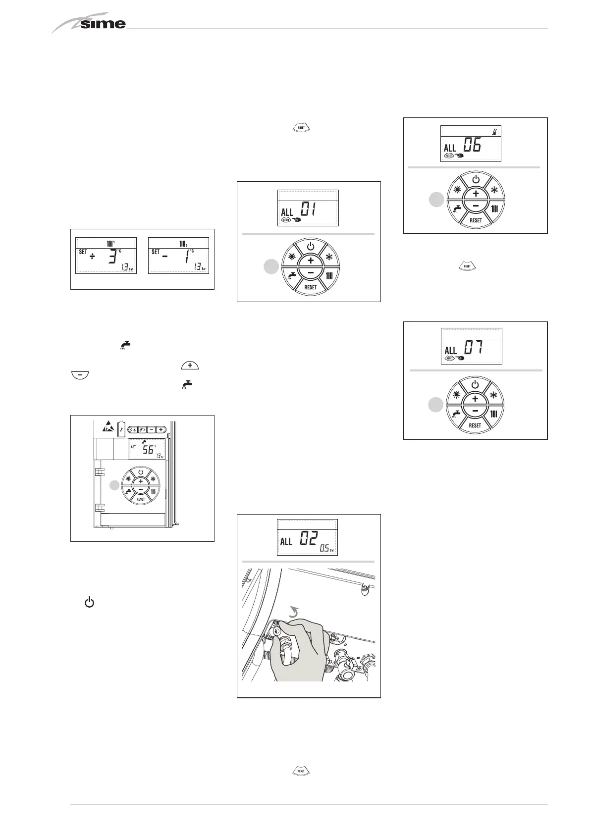
ANOMALIES AND SOLUTIONS
When there is a functioning anomaly, the di-
splay shows an alarm and the blue luminous
bar becomes red. Descriptions of the ano-
malies with the relative alarms and solutions
are given below:
– ALL 01 (fig. 28)
Press the key
of the controls (2) to
re-start the boiler.
If the anomaly persists, request the in-
tervention of qualified technical person-
nel.
– ALL 02 (fig. 28/a)
If the water pressure detected is lower
than 0.5 bar, the boiler will stop and the
display will show “ALL 02”.
Bring the pressure back to normal by ac-
ting on the loading knob. Lower the knob
and turn it anti-clockwise to open until
the pressure indicated by the display is
between 1 and 1.5 bars.
WHEN FILLING HAS BEEN COMPLE-
TED, CLOSE THE KNOB BY TURNING IT
CLOCKWISE.
If it is necessary to repeat the system
loading procedure, it is advisable to
contact qualified technical personnel to
check the seal of the heating system (to
check whether there are any leaks).
– ALL 03/ALL 04/ALL 05
Request assistance from qualified tech-
nical personnel.
– ALL 06 (fig. 28/c)
Press the key
of the controls (2) to
re-start the boiler.
If the anomaly persists, request assistan-
ce from qualified technical personnel.
– ALL 07 (fig. 28/d)
Press the key
of the controls (2) to
re-start the boiler.
If the anomaly persists, request assi-
stance from qualified technical person-
nel.
– From “ALL 08” to “ALL 29”
Request assistance from qualified tech-
nical personnel.
GAS CONVERSION
If it is necessary to change to a different
type of gas, request assistance only from
authorised technical personnel.
MAINTENANCE
Annual maintenance of the appliance
should be planned sufficiently in advance,
requesting the assistance of authorised
technical personnel.
DISPOSAL OF THE EQUIPMENT
(EUROPEAN DIRECTIVE 2002/96/CE)
Once it reaches the end of its operating life,
the equipment MUST BE RECYCLED in line
with current legislation.
IT MUST NOT be disposed of together with
urban waste.
It can be handed over to recycling centres, if
there are any, or to retailers that offer this
service.
Recycling prevents potential damage to the
environment and health. It allows to reco-
ver a number of recyclable materials, with
considerable savings in terms of money and
energy.
Apre
2
2
2
Circuito
riscaldamento 2
Circuito
riscaldamento 3
(impianto tre
zone)
Fig. 26/a
2
Circuito
riscaldamento 2
Circuito
riscaldamento 3
(impianto tre
zone)
Fig. 27
Apre
2
2
2
Circuito
riscaldamento 2
Circuito
riscaldamento 3
(impianto tre
zone)
APRE
Fig. 28/a
OPEN
Apre
2
2
2
Circuito
riscaldamento 2
Circuito
riscaldamento 3
(impianto tre
zone)
2
2
Circuito
riscaldamento 2
Circuito
riscaldamento 3
(impianto tre
zone)
Fig. 28
Apre
2
2
2
Circuito
riscaldamento 2
Circuito
riscaldamento 3
(impianto tre
zone)
2
2
Circuito
riscaldamento 2
Circuito
riscaldamento 3
(impianto tre
zone)
Fig. 28/d
Apre
2
2
2
Circuito
riscaldamento 2
Circuito
riscaldamento 3
(impianto tre
zone)
2
2
Circuito
riscaldamento 2
Circuito
riscaldamento 3
(impianto tre
zone)
Fig. 28/c
 Loading...


