Conexión de lectores biométricos a la central controladora
Connecting biometric readers to controller
www.simon.es
2
- Las líneas D0 y D1 son las líneas Wiegand y el número Wiegand se
envía a través de ellas.
- La línea RS485 (A, B) se usa para la conguración de transferencia
de huellas dactilares y del lector.
- Los lectores biométricos deben recibir la energía del controlador.
- Si usa otro suministro de energía para el lector biométrico, conecte
la toma de tierra (Gnd) de ambos dispositivos para asegurar la trans-
ferencia correcta de la señal Wiegand.
- Cuando haya conectado el lector y lo haya encendido, el LED parpa-
deará en naranja y emitirá dos pitidos. Esto indica que está encendido
y listo para su uso.
- El registro de la huella dactilar se realiza desde el software del orde-
nador. Se debe establecer la conexión entre los lectores biométricos
y el ordenador.
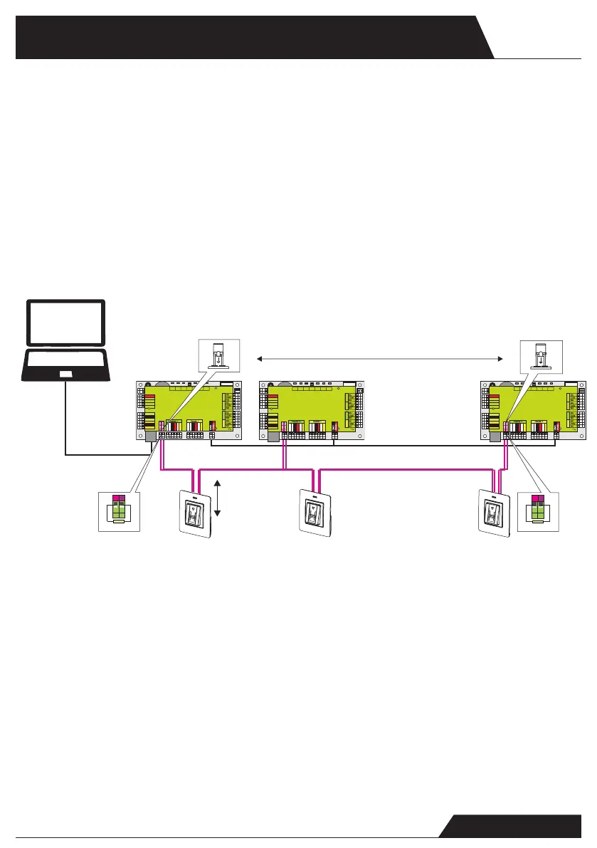
CONEXIÓN DE LECTORES BIOMÉTRICOS EN LA MISMA LÍNEA
RS485 CON LAS CENTRALES CONTROLADORAS (Art. 8902013-039)
- Los lectores biométricos se conectan a través del bus RS485, el mismo al
que están conectados los controladores EWS.
- El número máximo de unidades en una red (EWS + lectores biométricos)
es de 32.
- Si hay más de 32 unidades en una red, use un concentrador RS485 para
conectarlas.
- La línea RS485 se debe congurar en forma de cadena tipo margarita,
NO en forma de estrella. Si se debe usar una estrella en algunos puntos,
mantenga estas conexiones fragmentadas lo más cerca posible de la línea
central RS485. La longitud máxima de la conexión fragmentada depende
de la instalación (número total de dispositivos en la línea RS485, longitud
total del cable, terminación, tipo de cable...), por lo que se recomienda que
las conexiones fragmentadas tengan menos de 10 metros de longitud.
Recuerde que esto puede causar errores de comunicación con el software
del ordenador.
- El cable debe ser trenzado y apantallado, con una sección transversal
mínima de 0,5 mm .
- Conecte el hilo de tierra (0 V) de cada unidad a la línea RS485 usando un
tercer alambre en el mismo cable.
- La pantalla del cable de comunicación entre dos dispositivos se debe
conectar a TIERRA desde UN lateral de la línea RS485. Use el lateral que
tiene conexión a tierra para crear una red de toma de tierra.
TCP/IP
GND GND
RS485
Máx. 5m
Max. 5m
1 km máx./ 32 Unidades (Centrales controladoras+ lectores
biométricos)
1 km max / 32 Units (Access controls+biometric readers)
Ponga el puente (120 ohm) en posición cerrada en la primera
y la última central controladora de la red RS485
Put the jumper (120ohm) in closed position onthe rst and the last
controller on a RS485 network
RS485
PC
- The lines D0 and D1 are the Wiegand lines and the Wiegand
Number is sent through them.
- The RS485 line (A, B) is used for ngerprint transfer and reader
settings.
- The Biometric readers must be powered from the controller.
- If you use different power supply for the biometric reader,
connect the GND from the both devices to ensure correct transfer
of the wiegand signal
- When you have connected the reader and powered on, the LED
should ash in orange light + 2 beeps. This lets you know it’s on
and ready for use.
- Fingerprint enrollment is done from the PC Software.
Connection between the Biometric readers and the PC must be
established.
CONNECTING BIOMETRIC READERS IN SAME RS485
LINE WITH THE CONTROLLERS (Art. 8902013-039)
- The Biometric readers are connected through RS485 bus. The same
RS485 bus that the EWS controllers are connected to.
- Maximum units in one network (EWS + Biometric readers) is 32.
- If there are more than 32 units in one network, please utilize RS 485
HUB to connect.
- The RS485 Line should be congured in the form of a daisy chain,
NOT in a form of a star. If star must be used in some points, keep
the stubs from the RS485 backbone as short as possible. Maximum
length of the stub is dependant of the installation (total number of
devices in RS485 line (total cable length, termination, cable type...)
so recommendation is to keep stubs shorter than 5 meters, keeping
in mind that this can be possible reason for errors in communication
with PC software
- The cable must be twisted and shielded with a min. 0.2 mm2 cross
section.
- Connect the ground (0V) of each unit in the RS 485 Line using a
third wire in the same cable.
- The shield of the communication cable between two devices must be
connected to the EARTH from ONE side of the RS 485 Line.Use the
side that has earth connection to the building’s grounding network.
L
R55
C41
L2
R36
R
1
8
R25
R24
R10
C
3
4
L10
L
11
C18
C33
R
9
C42
C1
R5
R45
C43
C44
R28
R21
C45
D13
L
R4
6
C3
C5
R38
L
R14
ZD4
C32
R19
R37
C27
L6
C16
C15
RX4
D5
D10
R
32
R33 R35
R49
IC6
ZD5
ZD6
R
2
2
L3
R53
R34
TAS1
IC11
R15
IC15
R3
R4
L8
R47
FUSE1
IC8
R20
R16
R11
C2
X1
C4
IC7
ICN2
R1
C13
C12
ICN1
R2
3
R48
A
LD5
RE1 RE3
A
LD8
X3
IC1
C
6
U5
L5
L4
RE4RE2
A
LD6
A
LD9
L
R13
ZD1
R54
R50
6
IC12
R17
7
R62
D3
D2
RX
3
R2
LD21
IC2
R30
BAT
U1
IC
5
FUSE2
IC3
A
IC1
A
A
A
A
Free Led 1
Free Led 2
GND
12V out
D0
D1
Free Led 1
Free Led 2
GND
12V out
D0
D1
Door Sensor2
Door Sensor1
Exit Button1
Exit Button2
GND
GND
Free In 2 -
Free In 2 +
Free In 1 -
Free In 1 +
Rx
Tx
Busy
12V
5V
3.3V
System
OK
Door 1
Door 2
Free Out 1 Free Out 2
TCP/IP
Earth
12Vdc Out
L
R55
C41
L2
R36
R
1
8
R25
R24
R10
C34
L10
L
11
C18
C33
R9
C42
C1
R5
R45
C43
C44
R28
R21
C45
D13
L
R4
6
C3
C5
R38
L
R14
ZD4
C32
R19
R37
C27
L6
C16
C15
RX4
D5
D10
R
32
R33 R35
R49
IC6
ZD5
ZD6
R
2
2
L3
R53
R34
TAS1
IC11
R15
IC15
R3
R4
L8
R47
FUSE1
IC8
R20
R16
R11
C2
X1
C4
IC7
ICN2
R1
C13
C12
ICN1
R2
3
R48
A
LD5
RE1 RE3
A
LD8
X3
IC1
C
6
U5
L5
L4
RE4RE2
A
LD6
A
LD9
L
R13
ZD1
R54
R50
6
IC12
R17
7
R62
D3
D2
RX3
R2
LD21
IC2
R30
BAT
U1
IC
5
FUSE2
IC3
A
IC1
A
A
A
A
Free Led 1
Free Led 2
GND
12V out
D0
D1
Free Led 1
Free Led 2
GND
12V out
D0
D1
Door Sensor2
Door Sensor1
Exit Button1
Exit Button2
GND
GND
Free In 2 -
Free In 2 +
Free In 1 -
Free In 1 +
Rx
Tx
Busy
12V
5V
3.3V
System
OK
Door 1
Door 2
Free Out 1 Free Out 2
TCP/IP
Earth
12Vdc Out
50 ohm
50 ohm
 Loading...