EasyManua.ls Logo

Simple Motors Kit 8 - User Manual

Simple Motors Kit 8
16 pages
Print Icon
To Next Page IconTo Next Page
Loading...
Assembly instructions for kit #8
All rights reserved. 2001 Simple Motors, LLC www.simplemotor.com
1
Assembly Instructions: Kit #8
With Kit #8 you have two choices:
You may build each of the motors one at a time using separate assembly instructions for
each motor (this is the easier way).
-or-
You may assemble all parts on the board as shown in the picture above and switch between
the 4 motor circuits by re-soldering connections between parts. This option is described
below.
1. Insert the T-pin into one of the caps.
Question and Answer IconNeed help?

Do you have a question about the Simple Motors Kit 8 and is the answer not in the manual?

Overview

This document provides assembly instructions for Kit #8, which allows users to build and experiment with four different types of electric motors. The kit offers two main approaches: building each motor one at a time using separate instructions (easier) or assembling all parts on a single board and switching between the four motor circuits by re-soldering connections. The latter option is described in detail within this manual.

Function Description:

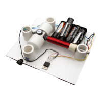
Kit #8 is designed to help users construct and understand the principles of various electric motors. It allows for the assembly of a basic motor, a reed switch motor, a reed switch motor with a transistor, a Hall Effect switch motor, and a motor with optical control. Each motor configuration demonstrates different methods of commutation (switching the electromagnet's field) to achieve continuous rotation. The core components include a rotor assembly with permanent magnets, an electromagnet (coil), and a sensing mechanism (reed switch, Hall Effect switch, or optointerrupter) to trigger the electromagnet at the correct time. A transistor is used in some configurations to amplify the switching signal, allowing for more robust operation or control with lower power sensors. The battery holder allows for experimentation with different voltage settings (1.5V, 3V, 4.5V, and 6V DC) to observe their effect on motor performance.

Assembly and Usage Features:

Rotor Assembly:

  1. T-pin and Cap Insertion: A T-pin is inserted into one of the caps, followed by the rotor core, pushed approximately 1/2" (10-12 mm) into the cap.
  2. Wooden Insert: A wooden insert is placed into the assembly.
  3. Pushpin and Second Cap: A pushpin is inserted into the other cap until fully seated, with about 1/4" (6-7 mm) sticking out.
  4. Final Rotor Assembly: Both caps are pushed together firmly to secure the T-pin. This step requires strength and caution to avoid bending the T-pin or self-injury.
  5. Magnet Attachment: Four magnets are glued to the flat surfaces of the rotor core, with the 'S' (South pole) facing outside (or a dimple facing inside for North pole). Users can start with two magnets on opposite sides. White glossy round labels are provided for aesthetic purposes and can be applied before magnet attachment using regular white glue or a glue stick. The T-pin should be straightened, and the rotor tested for free spinning between thumb and index finger.
  6. Disk Attachment: A disk, supplied with the kit, is cut out, and a hole is poked in its center. Glue is applied to the middle of the disk, and it is attached to the cap with the shorter axle (the one with the pushpin). Two sequins are slid onto the axle, acting as spacers between the disk and the stand, with their convex surfaces facing outwards. One sequin can also be used.

Stand and Electromagnet Assembly:

  1. Rotor Stand Insertion: The rotor is inserted into the stands marked with blue and silver stars. The stands are held, and the rotor is tested for free spinning. Final adjustments to the T-pin are made if necessary.
  2. Stand Gluing (Propeller Consideration): If a propeller is to be attached, the stand with the blue star should be glued as close to the edge as possible, potentially requiring the entire rotor assembly to be shifted. The stand with the silver star is glued to the board, covering the corresponding star and aligning its marks with the line on the board. Accuracy is crucial as super glue bonds instantly.
  3. Second Stand Gluing: The rotor is inserted into the stand marked with the blue star, and this stand is glued to the board, leaving a gap of about 1/16" (1/32" or 0.8 mm) on each side between the rotor and the stands. The rotor's free spin is re-tested. A rubber plug can be fixed as shown, and different items can be glued to its outer flat surface.
  4. Electromagnet Coil Winding: Two 9" (22-23 cm) pieces of wire are cut for the reed switch. The remaining wire on the spool is used to wrap around the nail (electromagnet core) between the tape and the head. One end of the wire is taped, leaving about 6" (15 cm) open. The wire is wound in one rotational direction (clockwise or counterclockwise), moving back and forth along the nail, ensuring it doesn't slide off. The second end is taped, leaving another 6" (15 cm) open. Approximately 3/8" (10 mm) of the wire tips are cleaned with fine sandpaper or a sharp knife to remove insulation.
  5. Electromagnet Test: The electromagnet is tested by connecting one wire to the "+" and the other to the "-" of a battery. If assembled correctly, the nail head should attract metal objects.
  6. Electromagnet Gluing: The electromagnet is glued to the board. The rotor is slowly turned to check if the magnets hit the electromagnet. If they do, the electromagnet is moved back until there is a 1/16" (1.5 mm) gap between it and the closest magnet on the rotor.

Sensor and Battery Holder Assembly:

Optointerrupter (for Optical Control Motor):

  1. Pin Identification: The four pins of the optointerrupter (Anode, Cathode for the LED; Emitter, Collector for the phototransistor) are identified. Incorrect connection will destroy the device.
  2. Wire Soldering: Four pieces of hook-up wire (8-9" or 20-23 cm each) are cut and stripped 3/8" (10 mm) at each end. These are soldered to the optointerrupter pins. Caution is advised to avoid overheating the optointerrupter during soldering; each lead should be soldered within 3 seconds, allowing the device to cool between connections.
  3. Optointerrupter Stand Gluing: The optointerrupter is glued to a square wooden stand, aligning with two marked lines.
  4. Optointerrupter Stand to Board Gluing: The optointerrupter stand is glued to the board. The disk blades should be centered in the slot as deep as possible without hitting the optointerrupter. After the glue dries, the cap with the disk is rotated to position one of the blades inside the slot, which will be adjusted later for optimal starting and speed.

Reed Switch (for Reed Switch Motors):

  1. ZNR (Optional): A ZNR (Zinc Oxide Varistor) can be added for higher voltages or more reliable motor operation, absorbing sparks in the reed switch and providing additional protection. If adding, skip to step 20.
  2. Reed Switch Wire Soldering: The two 9" magnet wires (cut earlier) are stripped 3/8" (10 mm) at both ends and soldered to the reed switch. Practice soldering if new to it.
  3. Reed Switch Insertion: The reed switch wires are inserted into the universal reed switch/Hall Effect switch stand. The wires are twisted as shown. Care is needed as the reed switch is fragile.
  4. ZNR with Reed Switch (if chosen): If adding the ZNR, the two magnet wires are stripped and soldered to the reed switch and the ZNR as shown.

Hall Effect Switch (for Hall Effect Switch Motor):

  1. Lead Bending and Wire Soldering: The leads of the Hall Effect switch are bent as shown. Three pieces of hook-up wire (8-9" or 20-23 cm each) are cut, stripped 3/8" (10 mm) at each end, and soldered to the Hall Effect switch (Supply, Output, Ground). Caution is advised to avoid overheating the Hall Effect switch during soldering; each lead should be soldered within 3 seconds, allowing the device to cool between connections.
  2. Lead Bending: The Hall Effect switch leads are bent 90 degrees with the branded side facing outside.
  3. Hall Effect Switch Insertion: The Hall Effect switch is inserted into the universal stand. The reed switch (if used) will be below it. Ensure the Hall Effect IC leads do not touch. Wires can be pushed into slots with a flat screwdriver. An alternative method from Kit #9 instructions (step 20) extends the Hall Effect IC to the top magnet, minimizing interference with the reed switch.
  4. Universal Stand Gluing: The universal stand (with Hall Effect and/or reed switch) is glued to the board, positioned in front of the magnets at the closest distance without the magnets hitting the switches during rotor rotation.

Battery Holder:

  1. Battery Holder Attachment: The battery holder is attached to the board. It requires four AA batteries and allows for 1.5V, 3V, 4.5V, and 6V DC operation using a jumper wire. The manual provides diagrams showing how the jumper wire configures the voltage by connecting different battery terminals. Users should inspect their battery holder for internal connections and find appropriate points for the jumper wire. Bare ends of the jumper wire are inserted between the spring and plastic case for good contact.

Transistor:

  1. Transistor Lead Identification: The Base (B), Collector (C), and Emitter (E) leads of the transistor are identified.
  2. Transistor Soldering Caution: Avoid overheating the transistor during soldering. Each lead should be soldered within 3 seconds, allowing the device to cool between connections.

Motor Circuit Assembly (after all components are on the board):

A. Reed Switch Motor:

  • Electromagnet Test: Connect electromagnet wires to the battery. If it doesn't repel magnets, switch wires.
  • Reed Switch Connection: Disconnect one electromagnet wire, connect it to the reed switch. Connect the other end of the reed switch to the battery.
  • Starting Voltage: Start with 1.5V. If the motor doesn't work, increase to 3V.
  • Troubleshooting: Ensure free rotor rotation, clean insulation, fresh batteries, and correct connections. Refer to the website's troubleshooting section.
  • Wiring Diagram: A diagram is provided for the reed switch motor.

B. Reed Switch Motor with Transistor:

  • Negative Battery/Reed Switch to Collector: Solder the negative (black) battery holder wire and one reed switch wire to the transistor's collector.
  • Other Reed Switch to Base: Solder the other reed switch wire to the transistor's base.
  • Electromagnet Test (Pre-soldering): Insert batteries. Briefly connect one electromagnet wire to the positive (red) battery holder wire and the other electromagnet wire to the emitter. If magnets aren't repelled, switch wires.
  • Electromagnet Soldering: If the motor works, remove batteries and solder electromagnet wires.
  • Capacitor (Optional): A capacitor can be connected as shown in the diagram to prolong reed switch life, but ZNR (step 20) usually provides better results.
  • Starting Voltage: Start with 1.5V. If the motor doesn't work, increase to 3V.
  • Troubleshooting: Ensure free rotor rotation, clean insulation, fresh batteries, and correct connections. Refer to the website's troubleshooting section.
  • CAUTION: Do not leave the motor connected to batteries if the rotor is stalled, as high current will overheat and potentially destroy the transistor.
  • Wiring Diagram: A diagram is provided for the reed switch motor with transistor.

C. Motor on a Hall Effect Switch:

  • Hook-up Wire to Collector: Solder one end of the remaining hook-up wire to the transistor's collector.
  • Ground Connection: Solder the other end of that wire, the negative (black) battery holder wire, and the Hall Effect switch's "ground" lead together. Twisting wires first makes soldering easier.
  • Hall Effect Output to Base: Solder the Hall Effect switch's "output" lead to the transistor's base.
  • Hall Effect Supply to Positive Battery: Solder the Hall Effect switch's "supply" lead to the positive (red) battery holder wire.
  • Electromagnet Test (Pre-soldering): Insert batteries. Briefly connect one electromagnet wire to the positive (red) battery holder wire and the other electromagnet wire to the emitter. If magnets aren't repelled, switch wires.
  • Electromagnet Soldering: If the motor works, remove batteries and solder electromagnet wires.
  • Starting Voltage: Start with 3V. If the motor doesn't work, increase to 4.5V.
  • Troubleshooting: Ensure free rotor rotation, clean insulation, fresh batteries, and correct connections. Refer to the website's troubleshooting section.
  • CAUTION: Do not leave the motor connected to batteries if the rotor is stalled, as high current will overheat and potentially destroy the transistor.
  • Wiring Diagram: A diagram is provided for the Hall Effect switch motor.

D. Motor with Optical Control:

  • Resistor Soldering: Solder the resistors (270 Ohm and 4.7K) together as shown, then solder them to the power transistor. Avoid overheating the transistor.
  • Optointerrupter Emitter to Resistor/Base: Solder the green wire from the optointerrupter (phototransistor emitter) to the connection point of the 4.7K resistor and the transistor's base.
  • Negative Battery/Collector to Resistor: Solder the negative (black) battery holder wire to the connection point where the transistor's collector connects to both resistors.
  • Optointerrupter Cathode to Resistor: Solder the black wire from the optointerrupter (LED cathode) to the open end of the 270 Ohm resistor.
  • Optointerrupter Collector/Anode to Positive Battery: Twist the ends of the white and red wires from the optointerrupter (phototransistor collector and LED anode) and the positive (red) battery holder wire together, then solder this connection.
  • Connection Check: Carefully check all connections. Direct connection of optointerrupter wires to the battery may destroy it.
  • Electromagnet Test (Pre-soldering): Insert batteries. Ensure one disk blade is in the optointerrupter slot, blocking light. Briefly connect one electromagnet wire to the positive (red) battery holder wire and the other electromagnet wire to the emitter. If magnets aren't repelled, switch wires.
  • Electromagnet Soldering: If the motor works, remove batteries and solder electromagnet wires.
  • Starting Voltage: Start with 3V. While holding magnets, slightly rotate the cap with the disk to find the best position for easy starting and fastest speed. If the motor doesn't work, increase to 4.5V.
  • Troubleshooting: Ensure free rotor rotation, clean insulation, fresh batteries, and correct connections. Refer to the website's troubleshooting section.
  • CAUTION: Do not leave the motor connected to batteries if the rotor is stalled, as high current will overheat and potentially destroy the transistor.
  • Wiring Diagram: A diagram is provided for the optical control motor.

Important Technical Specifications:

  • Rotor Core Insertion Depth: Approximately 1/2" (10-12 mm).
  • Pushpin Protrusion: Approximately 1/4" (6-7 mm).
  • Magnet Polarity: 'S' (South pole) facing outside or dimple (North pole) facing inside.
  • Rotor-Stand Gap: Approximately 1/16" (1/32" or 0.8 mm) on each side.
  • Electromagnet-Magnet Gap: Approximately 1/16" (1.5 mm).
  • Coil Wire Length: Two pieces of 9" (22-23 cm) for reed switch. Remaining wire for coil.
  • Wire Stripping Length: Approximately 3/8" (10 mm) for wire tips.
  • Hook-up Wire Length (Optointerrupter/Hall Effect): Four pieces of 8-9" (20-23 cm) each.
  • Soldering Time Limit: 3 seconds per lead for sensitive components (optointerrupter, Hall Effect switch, transistor) to prevent overheating.
  • Battery Type: 4 AA size batteries.
  • Voltage Settings: 1.5V, 3V, 4.5V, 6V DC, selectable via jumper wire in the battery holder.
  • Resistor Values (Optical Control): 270 Ohm and 4.7K Ohm.

Maintenance Features:

  • T-pin Straightening: The T-pin should be straightened if necessary to ensure free rotor spin.
  • Insulation Cleaning: Thoroughly clean insulation from wire tips before soldering to ensure good electrical contact.
  • Battery Freshness: Ensure batteries are fresh for optimal motor performance.
  • Rotor Free Rotation: Regularly check that the rotor spins freely without hitting any components.
  • Connection Checks: Verify all connections are secure and correct, especially if the motor is not working.
  • Troubleshooting: Refer to the "Troubleshooting" section on the Simple Motors website for assistance if the motor does not work.
  • Reed Switch Protection (Optional): A ZNR can be added to absorb sparks and prolong the life of the reed switch. A capacitor can also be used for this purpose.
  • Reed Switch Vibration Reduction: A self-sticking felt pad is attached to the reed switch stand to decrease vibration and sound.
  • Transistor Overheating Prevention: Avoid stalling the motor, as high current can overheat and destroy the transistor. Disconnect from batteries if stalled.

Simple Motors Kit 8 Specifications

General IconGeneral
BrandSimple Motors
ModelKit 8
CategoryEngine
LanguageEnglish

Related product manuals