Do you have a question about the Simple Motors Kit 6 and is the answer not in the manual?
Insert the T-pin into one of the caps.
Insert the rotor core into the cap, applying pressure to seat it approximately 1/2 inch.
Place the wooden insert into position within the assembled rotor components.
Insert the pushpin into the other cap, ensuring it protrudes about 1/4 inch.
Push the caps together firmly until the T-pin is secured.
Glue the magnets to the rotor core flat surfaces with the 'S' pole facing outwards.
Place the rotor assembly into the stands marked with blue and silver stars.
Glue the stands to the base, aligning marks and ensuring low friction for rotor spin.
Insert the nail into the stand with the green star and secure with glue if loose.
Wrap wire around the nail between the tape, leaving 6-inch ends, and clean tips.
Attach the electromagnet to the board, ensuring a 1/16-inch gap from the rotor magnets.
Bend the Hall Effect switch leads and solder wires to its terminals.
Insert the Hall Effect switch into its stand, ensuring leads do not touch.
Glue the Hall Effect switch holder to the board, positioning it near the magnets.
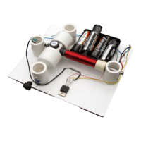
Attach the battery holder to the board for experimenting with different voltage settings.
Diagrams illustrate how to achieve 1.5V, 3V, 4.5V, and 6V using batteries and jumper wires.
Locate the Base (B), Collector (C), and Emitter (E) leads on the transistor.
Solder hook-up wires to the transistor and connect them to the battery holder and Hall Effect switch.
Connect the electromagnet wires to the battery holder and transistor emitter, testing polarity.
Start with 3V, test rotor spin, and troubleshoot if the motor does not work.
Avoid leaving the motor connected to stalled batteries to prevent transistor overheating and damage.
| Brand | Simple Motors |
|---|---|
| Model | Kit 6 |
| Category | Engine |
| Language | English |