ALARM CIRCUIT
Alarm Condition
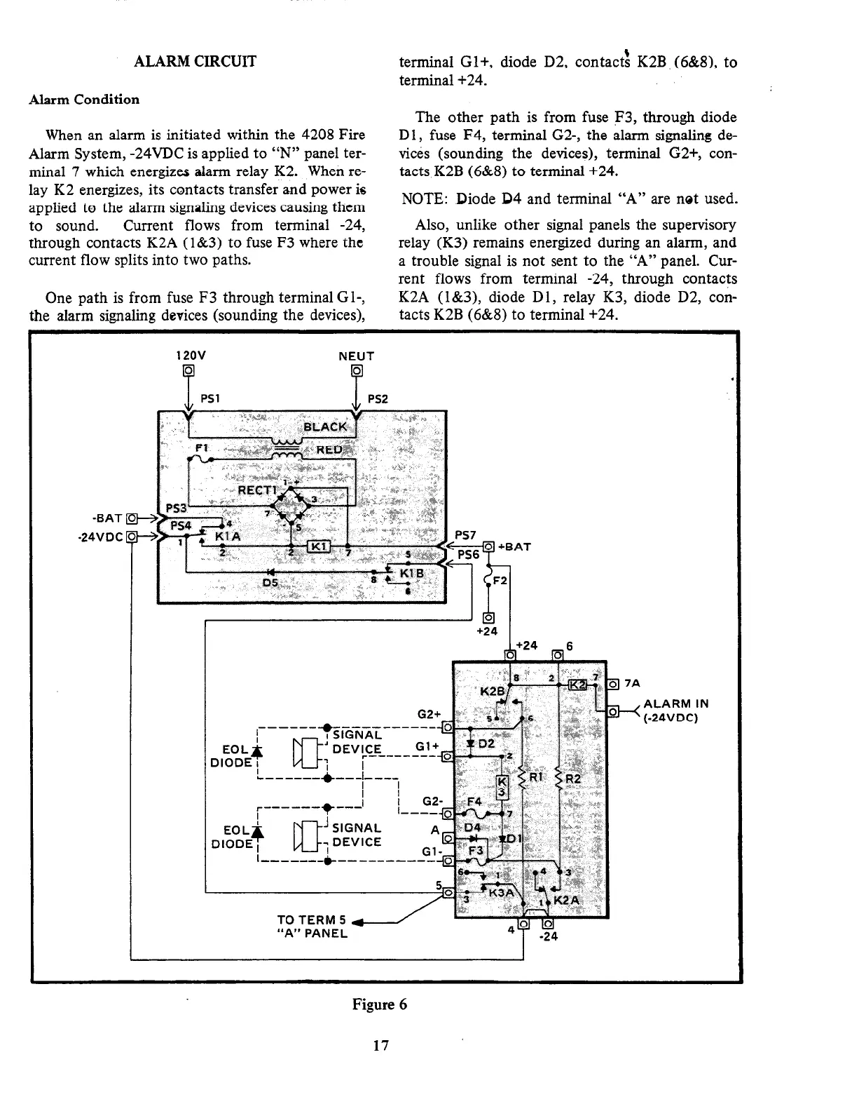
When an alarm is initiated within the 4208 Fire
Alarm System, -24VDC is applied to “N” panel ter-
minal 7 which energizes alarm relay K2. When re-
lay K2 energizes, its contacts transfer and power is
applied to the alarm signaling devices causing them
to sound.
Current flows from terminal -24,
through contacts K2A (l&3) to fuse F3 where the
current flow splits into two paths.
One path is from fuse F3 through terminal Gl-,
terminal Gl+, diode D2, contact: K2B. (6&8), to
terminal +24.
The other path is from fuse E3, through diode
D 1, fuse F4, terminal G2-, the alarm signaling de-
vices (sounding the devices), terminal G2+, con-
tacts K2B (6&8) to terminal +24.
NOTE: Diode D4 and terminal “A” are net used.
Also, unlike other signal panels the supervisory
relay (K3) remains energized during an alarm, and
a trouble signal is not sent to the “A” panel. Cur-
rent flows from terminal -24, through contacts
K2A (l&3), diode Dl, relay K3, diode D2, con-
the alarm signaling devices (sounding the devices),
tacts K2B (6&8) to terminal +24.
12ov
NEUT
-BAT
-24VDC
AT
TOTERM 5 4-A
“A” PANEL
Figure 6
17