SIGNAL CIRCUIT
P. C. module.
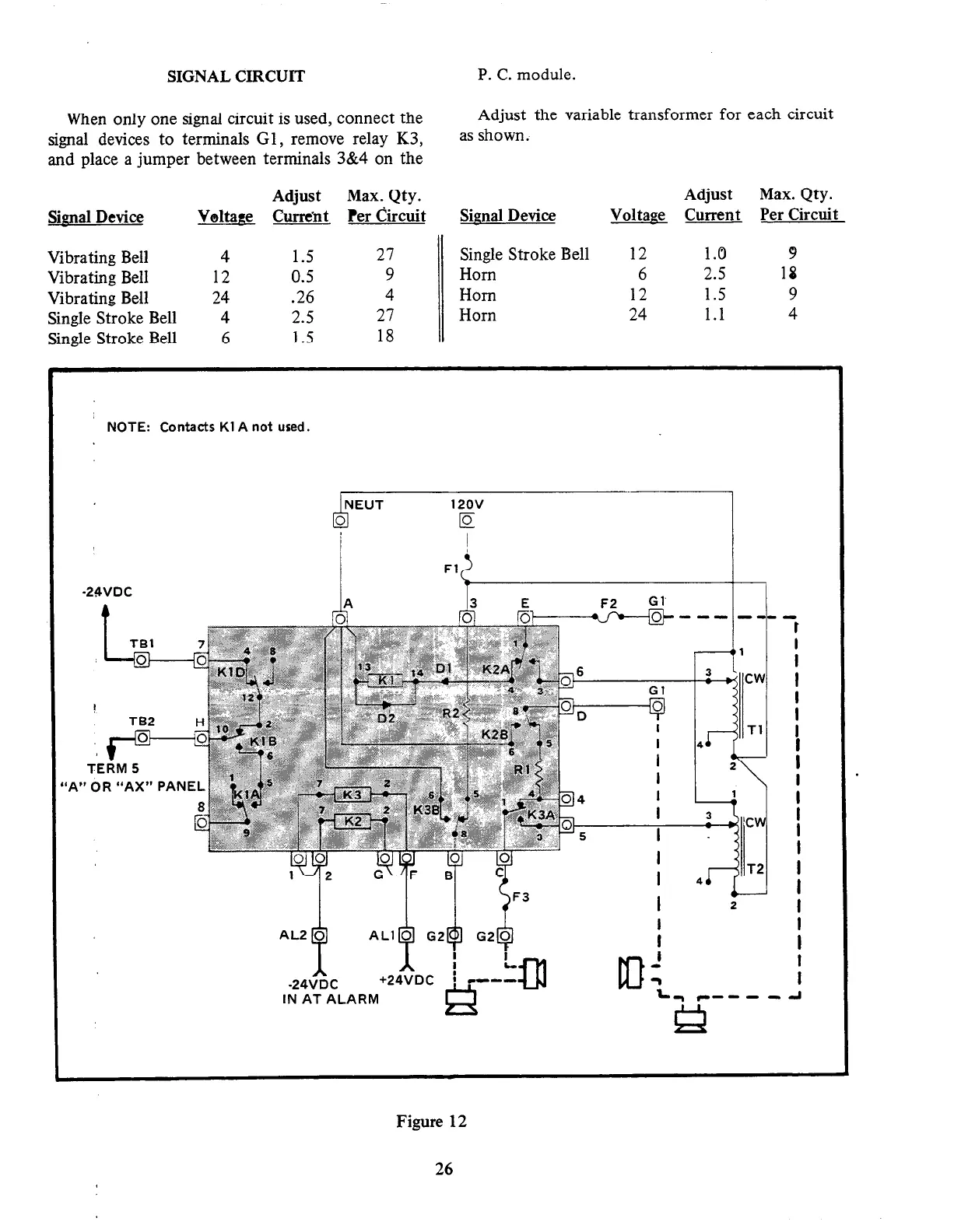
When only one signal circuit is used, connect the
signal devices to terminals Gl, remove relay K3,
and place a jumper between terminals 3&4 on the
Adjust the variable transformer for each circuit
as shown.
Adjust
Max. Qty.
Adjust Max. Qty.
Signal Device
V&age &u-r&t Per Circuit
Signal Device
Voltage Current Per Circuit
Vibrating Bell 4 1.5
27 Single Stroke Bell 12 1.0
9
Vibrating Bell 12 0.5
9 Horn 6 2.5
18
Vibrating Bell 24 .26
4 Horn 12 1.5
9
Single Stroke Bell 4 2.5
27 Horn 24 1.1
4
Single Stroke Bell 6 1.5
18
’ NOTE: Contacts Kl A not used.
Fl
I, t L
-24VDC
+24VDC
i CM--
IN AT ALARM
#
Figure 12
26