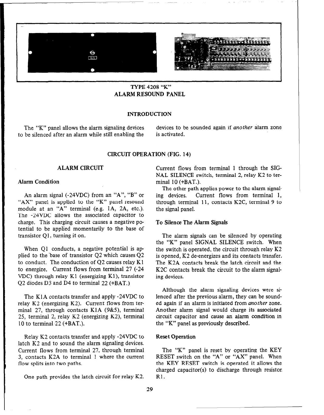
TYPE 4208 “K”
ALARM RESOUND PANEL
INTRODUCTION
The “K” panel allows the alarm signaling devices
devices to be sounded again if
another
alarm zone
to be silenced after an alarm while still enabling the
is activated.
CIRCUIT OPERATION (FIG. 14)
ALARM CIRCUIT
Alarm Condition
An alarm signal (-24VDC) from an “A”, “B” or
“AX” panel is applied to the “K” panel resound
module at an “A” terminal (e.g. lA, 2A, etc.).
The -24VDC allows the associated capacitor to
charge. This charging circuit causes a negative po-
tential to be applied momentarily to the base of
transistor Ql , turning it on.
When Ql conducts, a negative potential is ap-
plied to the ‘base of transistor Q2 which causes Q2
to conduct. The conduction of 42 causes relay Kl
to energize. Current flows from terminal 27 (-24
VDC) through relay Kl (energizing Kl), transistor
Q2 diodes D3 and D4 to terminal
22 (+BAT.)
The KlA contacts transfer and apply -24VDC to
relay K2 (energizing K2). Current flows from ter-
minal 27, through contacts KlA (g&5), terminal
25, terminal 2, relay K2 (energizing K2), terminal
10 to terminal -22 (+BAT.).
Relay K2 contacts transfer and apply -24VDC to
latch K2 and to sound the alarm signaling devices.
Current flows from terminal 27, through terminal
3, contacts K2A to terminal 1 where the current
flow splits into two paths.
One path provides the latch circuit for relay K2.
Current flows from terminal 1 through the SIG-
NAL SILENCE switch, terminal 2, relay K2 to ter-
minal 10 (+BAT.).
The other path applies power to the alarm signal-
ing devices.
Current flows from terminal 1,
through terminal 11, contacts K2C, terminal 9 to
the signal panel.
To Silence The Alarm Signals
The alarm signals can be silenced by operating
the “K” panel SIGNAL SILENCE switch. When
the switch is operated, the circuit through relay K2
is opened, K2 de-energizes and its contacts transfer.
The K2A contacts break the latch circuit and the
K2C contacts break the circuit to the alarm signal-
ing devices.
Although the alarm signaling devices were si-
lenced after the previous alarm, they can be sound-
ed again if an alarm is initiated from
another
zone.
Another alarm signal would charge its associated
circuit capacitor and cause an alarm condition in
the “K” panel as previously described.
Reset Operation
The “K” panel is reset by operating the KEY
RESET switch on the “A” or
“AX”
panel. When
the KEY RESET switch is operated it allows the
charged capacitor(s) to discharge through resistor
Rl.
29
 Loading...


