Installation,
Confinued
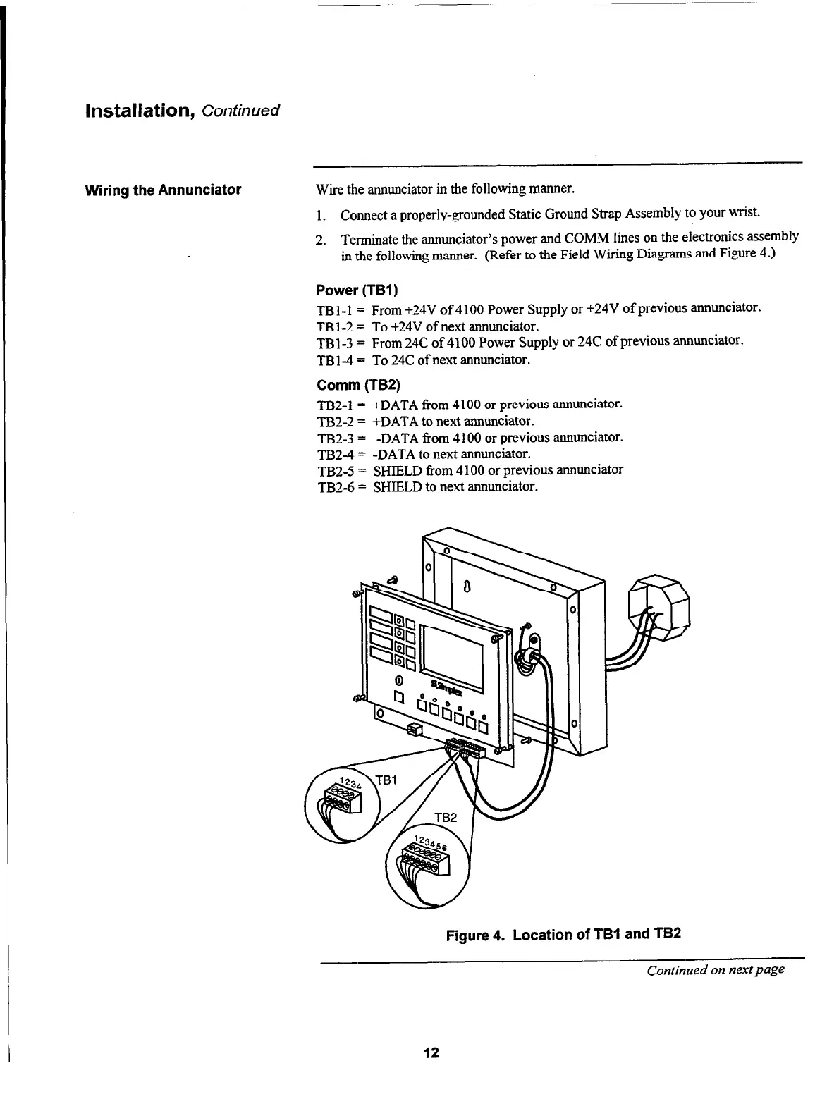
Wiring the Annunciator Wire the annunciator in the following manner.
1. Connect a properly-grounded Static Ground Strap Assembly to your wrist.
2. Terminate the annunciator’s power and COMM lines on the electronics assembly
in the following manner. (Refer to the Field Wiring Diagrams and Figure 4.)
Power (TBI)
TB l-l = From +24V of 4 100 Power Supply or +24V of previous annunciator.
TB l-2 = To +24V of next annunciator.
TB l-3 = From 24C of 4100 Power Supply or 24C of previous annunciator.
TB l-4 = To 24C of next annunciator.
Comm (TB2)
TB2-1 = +DATA from 4 100 or previous annunciator.
TB2-2 = +DATA to next annunciator.
TB2-3 = -DATA from 4 100 or previous annunciator.
TB2-4 = -DATA to next annunciator.
TB2-5 = SHIELD from 4 100 or previous annunciator
TB2-6 = SHIELD to next annunciator.
Figure 4. Location of TBI and TB2
Continued on next page
12