3
579-1190 Installation instructions
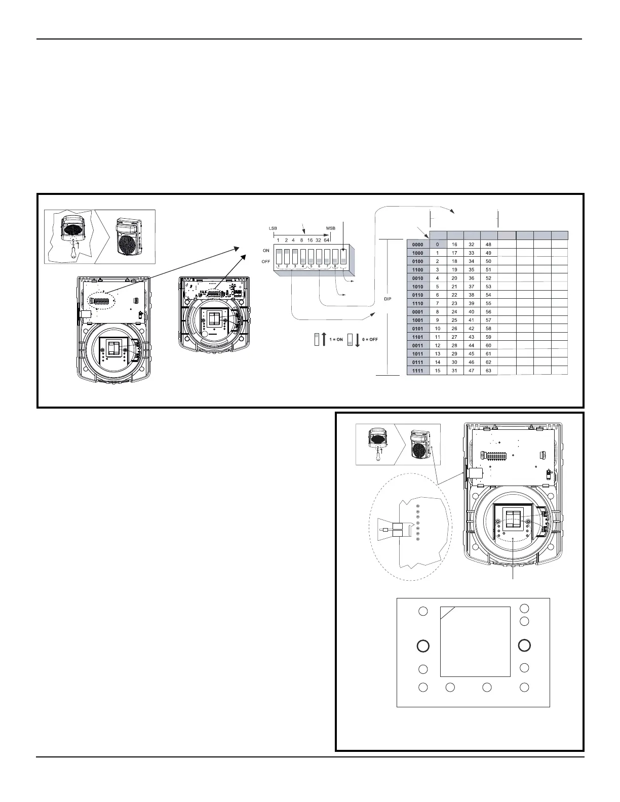
Setting the address DIP switch
Each addressable TrueAlert IDNAC notification appliance has a unique address that is set using an eight-position DIP switch
(ADDR1). Up to 127 unique addresses can be assigned to an SLC, however, the total appliance loading available may be less due to
appliance current requirements.
To Set the address:
1. Unclip the appliance from the backplate by inserting a number 2 Phillips screwdriver, or a similar sized object into the opening at
the bottom of the cover. See Figure 3.
2. Use a small screwdriver or pen to set the switches.
3. Record the set address.
4. DIP switch position 8 determines whether this appliance is viewed by the system as an 'ALARM' (OFF) or 'ALERT' (ON) type of
appliance. Confirm the setting for the appliance at this address with the FACP system configuration documentation.
5. DIP position 9 selects white flash color (standard - OFF), or tinted strobe power level (ON) for use with add-on domes.
Figure 3. Setting the DIP switch address
Setting the strobe candela setting
Figure 4. Setting the strobe and appliance configuration
1. Jumpers are factory set as FACP. Leave the appliance at this setting if
the candela setting is to be programmed from a 4100ES FACP. The
candela setting is visible through the slot on the side of the appliance.
2. If manual selection is required, pull up the candela flag and position the
pins to select the correct candela setting: 15, 30, 75, 110, 135, 185
candela, or FACP.
3. The candela ratings vary when colored lenses are used. Consult the
TrueAlert ES WM S/V Colored Lens
document (579-1192) for the
specific candela ratings.
4. When the appliance is mounted, the candela rating is visible through
the slot on the side of the appliance.
Note: To avoid a programming mismatch trouble, an authorized service personnel
must program one of the 6 candela outputs for each appliance. To set the
candela through the Programmer, set it to FACP. For additional information
refer to the 4100ES Programmer’s Manual (574-849).
Audio circuit configuration, S/V and SO
Move the wire harness position to the correct terminal post for audio
circuit voltage and power tap selection. See Figure 4 and the speaker
table on the next page.
To access the switches:
Alarm/
Alert
DIP switch 5 through 7
9
White
Tinted
S/V Appliance
SO Appliance
0010 1010 0110 1110
64
65
66
67
68
69
70
71
72
73
74
75
76
77
78
79
80
81
82
83
84
85
86
87
88
89
90
91
92
93
94
95
96
97
98
99
100
101
102
103
104
105
106
107
108
109
110
111
112
113
114
115
116
117
118
119
120
121
122
123
124
125
126
127
0000 1000 0100 1100
S/V
only
DIP switch shown is
set at address 7.
DIP switch value:
Reserved for
future use.
switches.
Candela
selection jumper
and candela rating
To access the switches:
Make the audio circuit voltage and
power tap selection here
C
W3
H
G
B
AD E F
T1
Audio power
TAP pins
(S/V & SO)
70V 1W
70V W/2
70V W/4
70V 2W 25V W/4
25V W/2
25V 1W
25V 2W
CD5 (FACP)
CD4 (15)
CD3 (30)
CD6 (135)
CD7 (185)
CD2 (75)
CD1 (110)

 Loading...