EasyManua.ls Logo

Simplicity SOVEREIGN 3415S - Starter-Generator Belt Adjustment; Carburetor Adjustment

Simplicity SOVEREIGN 3415S
40 pages
Print Icon
To Next Page IconTo Next Page
To Previous Page IconTo Previous Page
Loading...
I
i
i
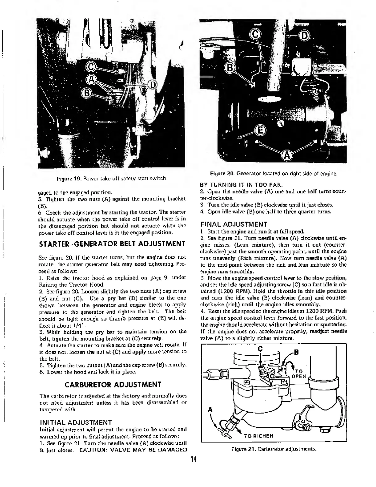
Figure
19.
Power
take
oil
safely
start
switch
yag&cl
ic
the
engaged
position,
5-
Tighten
the
two
nuts
[A}
against
the
mounting
bracket
(B),
6.
Check
the
adjustment
by
starling
the
tractor.
The
starter
should
actuate
when
the
power
take
oH
control
lever
is
in
the
disengaged
position
but
should
not
actuate
when
the
power
take
off
control
lever
t£
in
the
engaged
position.
STARTER-GENERATOR
BELT
ADJUSTMENT
See
figure
20.
If
the
starter
turns,
hut
the
engine
does
not
rotate,
the
starter
generator
belt
may
need
tightening.
Pro¬
ceed
as
follows:
1-
Raise
the
tractor
hood
as
explained
on
page
9
under
Raising
the
Tractor
llood-
2.
S
ee
figure
20.
Loosen
slightly
the
two
nuts
(A)
cap
screw
(0)
and
nut
(C).
Use
a
pry
bar
(D)
similar
to
the
one
shown
between
the
generator
and
engine
block
to
apply
pressure
to
the
generator
and
tighten
the
belt.
The
belt
should
be
Light
enough
so
thumb
pressure
at
(£}
will
de¬
flect
it
about
3/4
r
'
-
3-
While
holding
the
pry
bar
to
maintain
tension
on
the
belt,
tighten
the
mounting
bracket
at
(C)
securely.
4.
Actuate
the
starter
to
make
sure
the
engine
will
rotate.
If
it
does
not,
loosen
the
nut
at
(C)
and
apply
more
tension
to
the
belt.
5.
Tighten
the
two
nuts
at
(A)
and
the
cap
screw(B)
securely.
6.
Lower
the
hood
anti
lock
it
in
place.
CARBURETOR
ADJUSTMENT
The
carburetor
is
adjusted
at
the
factory
and
normally
does
not
need
adjustment
unless
it
has
been
disassembled
or
tampered
with.
INITIAL
ADJUSTMENT
Initial
adjustment
will
permit
the
engine
to
be
started
and
warmed
up
prior
to
final
adjustment-
Proceed
as
follows:
1.
S
ee
figure
21.
Turn
the
needle
valve
(A)
clockwise
until
it
just
closes
CAUTION:
VALVE
MAY
B£
DAMAGED
Figure
20-
Generator
located
on
right
side
of
engine,
BY
TURNING
IT
IN
TOO
FAR.
2.
Open
the
needle
valve
(A)
one
and
one
half
turns
coun¬
ter-clockwise,
3.
Turn
the
idle
valve
(B)
clockwise
until
it
just
closes.
4.
Open
idle
valve
(B)
one
half
to
three
quarter
turns.
FINAL
ADJUSTMENT
1.
Start
the.engine
and
run
it
at
full
speed.
2.
See
figure
21.
Turn
needle
valve
(A)
clockwise
until
en¬
gine
misses,
(Lean
mixture),
then
turn
it
out
(counter¬
clockwise)
past
the
smooth
operating
point,
until
the
engine
runs
unevenly
(Rich
mixture).
Now
turn
needle
valve
(A)
to
the
mid-point
between
the
rich
and
lean
mixture
so
the
engine
runs
smoothly.
3.
Move
the
engine
speed
control
lever
to
the
slow
position,
and
set
the
idle
spaed
adjusting
screw
(C)
so
a
fast
idle
is
ob¬
tained
(1200
RPM).
Hold
the
throttle
in
this
idle
position
and
turn
the
idle
valve
(B)
clockwise
(lean)
and
counter¬
clockwise
(rich)
until
the
engine
idles
smoothly.
4.
Reset
the
idle
speed
so
the
engine
idles
at
1200
RFM.
Push
the
engine
speed
control
lever
forward
to
the
Tast
position,
the
engine
should
accelerate
without
hesitation
or
sputtering.
If
the
engine
does
not
accelerate
property,
readjust
needle
valve
(A)
to
a
slightly
richer
mixture.
14