4
2.0 PLANNING THE INSTALLATION
2.1 Package Contents
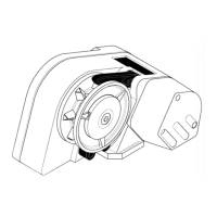
Capstan
Mounting Studs, Washers, Nuts & 'O' Ring
Clamping Plate
Mounting Template
Safety Instructions
Installation Warning Label
Instruction Manual
2.2 Additional Requirements
Each capstan installation requires :
a. A solenoid for a single direction installation. (Unless the
High Load Foot Switch only is used)
b. A control switch (or switches) by preference.
c. A breaker/isolator for overload protection which can also be
used as a main isolating switch. (Simpson-Lawrence
recommend the breaker/isolators listed under 3.0
Accessories)
d. The following tools:
Capstan Installation
Flat Blade Screwdriver
10mm (
3
/8") Diameter Drill
13mm A/F (
1
/2") Spanner (Wrench)
Jig Saw or Trepanning Tool
Wiring Installation
Flat Blade Screwdriver
Crimping Pliers / Wire Stripper
13mm A/F (
1
/2") Spanner or Socket
8mm A/F (
5
/16") Spanner or Socket
e. Marine grade silicone sealant. DO NOT use permanent
adhesive/sealant.
f. Suitable electrical cable and crimp terminals.
2.3 Electric Cable Selection
To achieve the best performance and safeguard your electrical
system, it is essential that any electric capstan is fitted with
sufficiently large diameter cable to cope with the current draw
imposed upon it and, to keep the voltage drop within acceptable
limits. In any circumstance, voltage drop due entirely to cable
resistance should not exceed 5%, roughly 0·5V for a 12V
installation and 1·0V for a 24V one.
The following tables give recommended cable sizes. The
recommendations are based on the total length of cable
required, from the battery to the capstan and back to the
battery, following the route of the cables. (See the Wiring
Diagram for the definition.)
DO NOT confuse Cable Length with the length of the vessel!
3.0 ACCESSORIES
Item List Number
Breaker/Isolator (70 Amp) 12V Installation 0050711
Breaker/Isolator (50 Amp) 24V Installation 0050710
12 Volt Solenoid Single direction 0052505
24 Volt Solenoid Single direction 0052506
Foot Switch Single direction 0052514
High Load Foot Switch Single direction 0052516
USA list number for above (Black) LEWP49C
USA list number for above (White) LEWP49CW
METRIC or STARTER CABLE
Voltage Cable Length Size
m (ft.) (mm²)
18.0m (60ft.) 25
12 27.0m (90ft.) 35
37.0m (120ft.) 50
18.0m (60ft.) 6
24 27.0m (90ft.) 10
37.0m (120ft.) 16
AMERICAN CABLE
Voltage Cable Length Size
m (ft.) (AWG)
18.0m (60ft.) 2
12 27.0m (90ft.) 1
37.0m (120ft.) 1/0
18.0m (60ft.) 8
24 27.0m (90ft.) 8
37.0m (120ft.) 6
Thin wire of 1·5mm² cross sectional area, 21/0·30 PVC covered
(American equivalent 14 AWG) is required for the control switch
circuits. This is used to connect the switch(es) to the
solenoid(s).