14
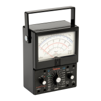
6. Connect the test leads across the resistance which is to be measured. If
there is a “forward” and “backward” resistance, such as with diodes, ob-
serve polarity in the lead connections to control each direction of test.
With the polarity switch in the + DC position, the + jack will provide a
positive potential referred to COM – jack. Setting the switch to the – DC
position will reserve this measuring potential.
7. Read the indication on the OHMS arc at the top of the dial. Note that the
arc reads from right to left for increasing values.
8. Multiply the reading by the multiplier factor indicated at the switch posi-
tion; the result is the resistance value in ohms. “K” on the dial and panel
stands for “times one thousand”.
NOTE:
The resistance of nonlinear components will measure as different val-
ues on different ranges of the 160. For example, a diode could measure 80
the R x 1 range, and 300 on the R x 10 range. This is normal and is the
result of the diode characteristic. The difference in readings does not indicate
faulty operation of the ohmmeter circuit.
4.11
Direct Current
Measuremen
t
1. Do not switch the range setting of the Range or Polarity Switches while
the circuit under measurement is energized.
2. Never disconnect the test leads from the circuit under measurement while
the circuit is energized.
3. Always turn the power off and discharge all the capacitors before the
setting of the switches is changed, or the leads disconnected.
4. Never exceed the Circuit-To-Ground voltage of the Instrument (1,000 V
max: Table 1-1, Rated Circuit-Ground Voltage).
5. Always connect the Instrument in series with the ground side of the cir-
cuit.
6. In all direct current measurements make certain the power to the circuit
being tested has been turned off before connecting and disconnecting
test leads or restoring circuit continuity.
4.12
Measuring
Direct
Currents,
50 µA
Range
Never connect the test leads directly across any source of voltage when the
160 is used for current measurements. This will damage the Instrument.
1. Connect the black test lead to the COM – jack, and the red test lead to the
+ 50 mA jack.
2. Set the range switch at 50 mA (common with 50 VDC).
3. With the circuit power turned off, open the circuit at the point where cur-
rent is to be measured. Connect the Instrument in series with the circuit,
observing proper polarities when making connection.
4. Turn on power to the circuit being measured. If the pointer is deflected to
the left of zero, the polarity is opposite to that anticipated. Turn power off