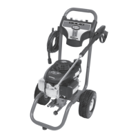
J.
Pump Inl
et
K. Quick Connect Nozzles
L.
Nozzle Ho
lder
M. Top Handle
BASIC
ELEMENTS
OF
AN
ENGINE
Refer
to
the
En
gine O
wn
e
r'
s Manual for location and operation
of
engine controls.
Choke Control: Opens and closes carburetor choke valve.
Sta
rt
er Grip: Pulling starter grip operates recoil starter to crank engine.
Engine
Swi
tc
h:
Enables and disables ignition system.
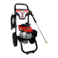
ASSEMBLY
INSTRUCTIONS
(FIG.
2-4)
1. Locate and remove
all
loose parts from the carton.
2. Cut four corners
of
the carton from top
to
bottom
and
lay the panels flat.
3.
Slide the handle assembly
(G)
onto the frame (H).
NO
TI
CE: Risk
of
personal injury. Avoid placing hands between handle and frame
when assembling to prevent pinching.
4. Align holes
in
the top handle (M) with the mounting holes
in
the handle
assembly
(G)
.
5.
Insert saddle bolts
(DD)
through aligned holes and secure top handle
to
handle
assembly with knobs
(EE)
. Tighten until snug.
6. Remove colored quick connect nozzles
(K)
from plastic bag and insert them
into correct grommet on the nozzle holder
(L)
. NOTE: Nozzles
are
color coded
to match colored nozzles on panel.
7. Connect wand
(E)
to gun
(D)
. Tighten securely.
8. Attach high pressure hose
(C)
to
gun
(D)
. Tighten securely .
•
·
~
! \
i
:
NO
TI
CE:
The
engine
is
shipped without oil. Before starting engine,
add
the oil
provided. Damage to the engine will occur
if
the engine is run without oil, this
damage will
not
be
covered under
warranty.
11-
ENG