Diagram 4
Carefully remove the electrode from the assembly to examine for cracks in the porcelain.
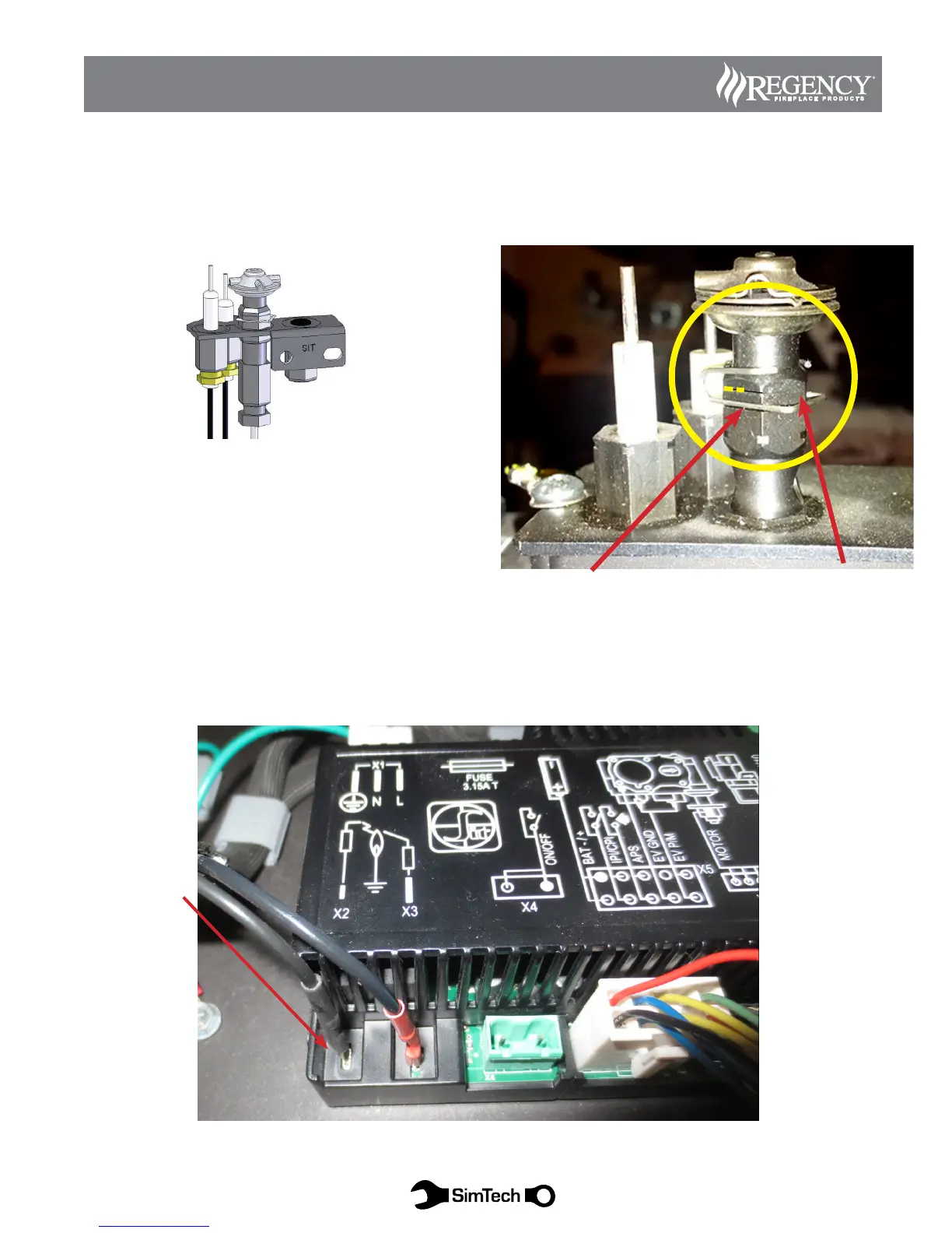
Remove pilot hood ground clip and hood, clean ground contact points from hood to assembly.
Examine electrode wire and connector for breaks or abrasion.
Pilot Ground Clip
Spark Electrode
Connection X2
Clean ground contact points from hood
to assembly
Diagram 5
Confirm the igniter wire is properly connected at terminal X2 and check for any breaks in the wire or connector.
Check Igniter Wire Connection
Pilot Assembly is comprised of three parts:
Pilot hood - Splits the flame into two (2) for burner and flame
sensor
Igniter - provides spark to the pilot hood
Flame Sensor - Rectifies the pilot. When lit, carries the voltage to
the IFC module to stop sparking and allows main burner to open.
Without proving the pilot, igniter will still spark and burner will
not turn on.
37
SUREFIRE ELECTRONIC IGNITION SYSTEM
S.I.T. PROFLAME 2 TROUBLESHOOTING
SimTech Proflame II