63
MAXITROL GV60 IGNITION SYSTEM
TROUBLESHOOTING
Maxitrol GV60
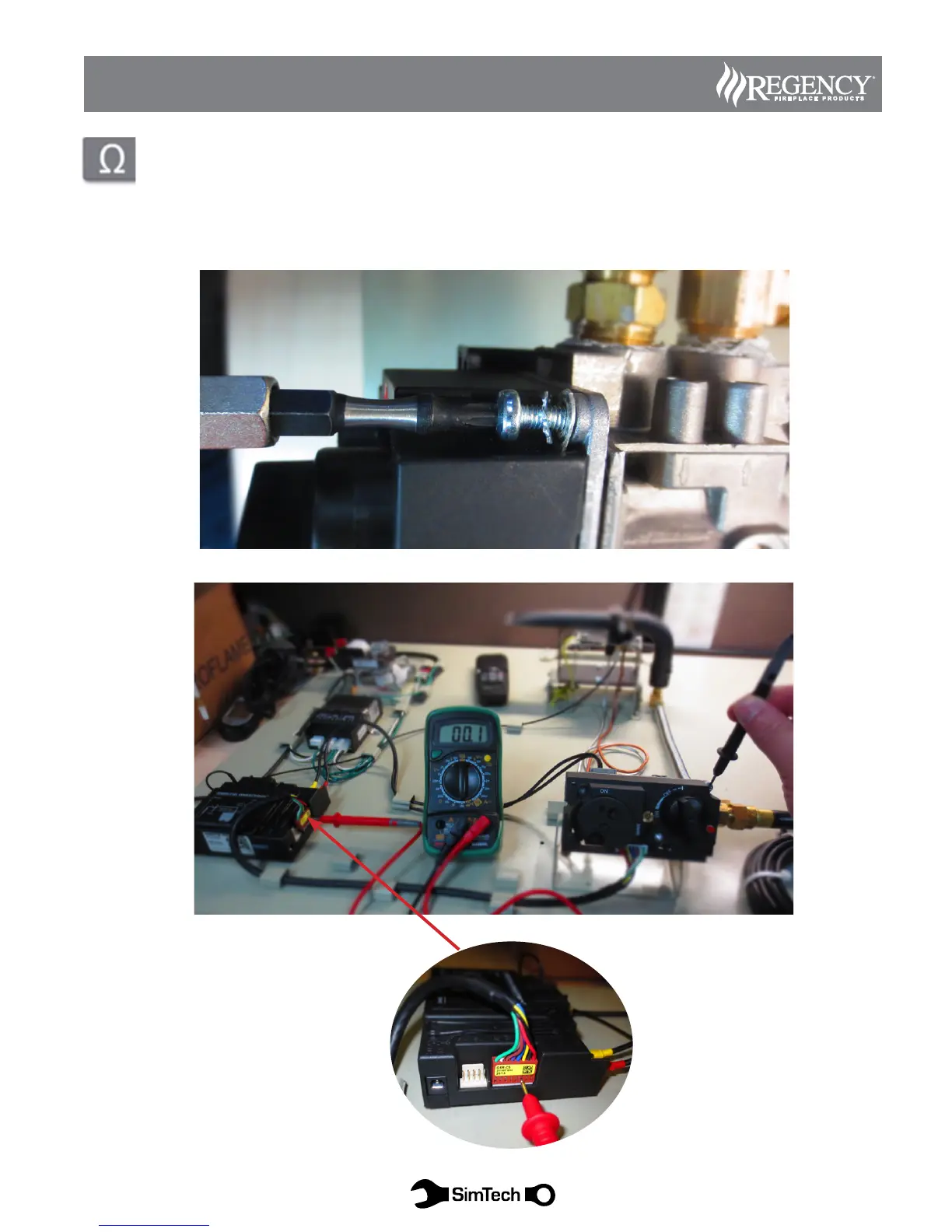
Diagram 8: Test ground connection at valve.
a.) Set meter to Resistance in the lowest range available.
b.) Place (+) Positive probe on valve ground lug (See Diagram 8 for location)
c.) Place (-) Negative probe to the yellow wire terminal on the 5 wire connector to the receiver (See Diagram 8a for location)
d.) Meter should read under 60 milliohms. ( See Diagram 8a)
e.) If open circuit, or greater than 60 milliohms remove valve ground lug screw (Torx-20), lightly sand both sides, re-
assemble and test again.