DC Inverter UNI SPLIT Series
Duct
Type Unit
12
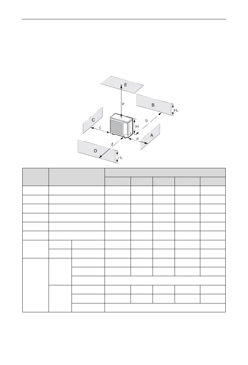
2.1.4 Diagram of Unit Installation Space and Location
(1) Diagram of installation space and location for outdoor unit (Notice: for best
performance of the outdoor unit, make sure its installation space
conforms to the following installation dimensions).
1) When one outdoor unit is to be installed.
A~E H
b
H
d
H
(mm)
a b c d e
B — — ≥100 — — —
A,B,C, — ≥300 ≥100 ≥100 — —
B,E — — ≥100 — — ≥1000
A,B,C,E — ≥300 ≥150 ≥150 — ≥1000
D — — — — ≥1000 —
D,E — — — — ≥1000 ≥1000
B,D
H
b
<H
d
H
d
>H — ≥100 — ≥1000 —
H
b
>H
d
H
d
<H — ≥100 — ≥1000 —
B,D,E
H
b
<H
d
H
b
≤1/2H — ≥250 — ≥2000 ≥1000
1/2H<H
b
≤H — ≥250 — ≥2000 ≥1000
H
b
>H Prohibited
H
b
>H
d
H
d
≤1/2H — ≥100 — ≥2000 ≥1000
1/2H<H
d
≤H — ≥200 — ≥2000 ≥1000
H
d
>H Prohibited