EasyManua.ls Logo

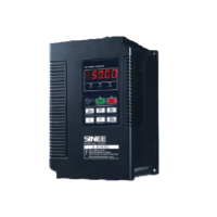
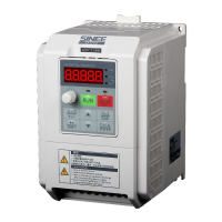
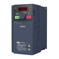
Sinee EM303A-015G/018P-3CB User Manual

Sinee EM303A-015G/018P-3CB
139 pages
To Next Page IconTo Next Page
Page #1 background imageLoading...
Page #1 background image
User Manual
EM303A General Purpose Inverter
1
Preface
Thank you for purchasing EM303A series inverter.
Document No.: 31010005
Issue Date: 06/06/2013
EM303A is a general purpose inverter (Speed Sensorless Vector Control). It helps an
induction motor to achieve not only the speed regulation standard of a DC motor, but also
the control ability of a torque motor, and the motion control system is optimized with
quick response, precise control and system stability.
The updates of EM303A:
1. Support Modbus RTU standard communication protocol.
2. Support RS485 master-slave communication control mode, numeric synchronized
control achieved.
3. Numeric input terminals support F/R logic control, delay input control, and etc.
4. Numeric output terminals support PWL/pulse output, F/R logic output and delay output,
and etc.
5. Analog input signals VS/IS/VF/IF can be programmed as numeric inputs, numeric
terminals expansion control achieved.
6. With filtering, analog input signals VP/VS/IS/VF/IF can actively avoid analog signals
interference and drift.
7. User can easily define the display of function code menus.
8. Run, stop and parameters setting status can program the displayed parameters
independently.
It is the duty of any user to perform the appropriate, correct installation or configuration
of the optional parameters of the devices. Neither SINEE nor its distributors shall be
responsible or liable for misuse of the information contained herein or mismatching the
inverter with the motor.
In the interests of commitment to a policy of continuous development and improvement,
SINEE reserves the right to update the specification of the product or its performance, or
the content herein without notice.

Table of Contents

Question and Answer IconNeed help?

Do you have a question about the Sinee EM303A-015G/018P-3CB and is the answer not in the manual?

Sinee EM303A-015G/018P-3CB Specifications

General IconGeneral
CategoryInverter
Rated Power1500W
Peak Power3000W
ModelEM303A-015G/018P-3CB
Input Voltage24V DC
Output Voltage220V AC
Output Frequency50Hz
Efficiency90%
Protection FeaturesOverload, Over Voltage, Short Circuit, Over Temperature
CoolingFan
Operating Temperature-10°C to 50°C

Summary

Safety Information

Safety Precautions

Provides essential precautions for safe operation and installation of the inverter.

Wiring

Danger

Highlights critical dangers and warnings related to electrical hazards during wiring.

Caution

Lists important cautionary notes to prevent damage or hazards during wiring.

Trial Operation

Trial Operation Safety

Highlights critical dangers and cautions during trial operation.

Maintenance and Inspection

Maintenance Safety

Emphasizes dangers and precautions related to inverter maintenance and inspection.

Other

Danger

Warns against modifying the inverter and highlights user responsibility for damages.

1.3 EM303A Operation Status Definition

1.3.2 Control Modes of Inverter

Explains different inverter control modes: V/F, SVC0, and SVC1.

2 Installation

Installation Site Considerations

Site Requirements

Lists environmental conditions, temperature, and ventilation needs for installation.

Installation Precautions

Advises protective measures during installation to prevent foreign matter ingress.

Installation Direction and Space

3 Wiring

3.1 Connections to Peripherals

Shows a diagram illustrating connections between EM303A and its peripherals.

3.2 Wiring Main Circuit Terminals

Main Circuit Terminal Block

Presents diagrams of the main circuit terminal blocks for different EM303A models.

Main Circuit Terminal Functions

Lists the functions of the main circuit terminals for proper connection.

Standard Wiring of Main Circuit

Wiring Main Circuit on Input Side

Installing a Circuit Breaker

Details the requirements for installing a circuit breaker on the input side for protection.

Installing a Leakage Circuit Breaker

3.2.5 Wiring the Output Side of Main Circuit

Connecting the Inverter to Motor

Provides instructions on connecting the inverter output terminals to the motor and checking rotation direction.

Output Wiring Precautions

Critical Warnings

Warns against connecting power to outputs, shorting, or using capacitors/switches.

3.2.6 Main Circuit Cable and Terminal Screw Size

3.2.7 Ground Wiring

3.3 Wiring Control Circuit Terminals

3.3.1 Control Circuit Terminals

Lists the control circuit terminals available on the EM303A PCBA.

3.3.2 Function and Wiring of Control Circuit Terminals

3.3.2.1 Wiring the Analog Input Terminals

3.3.2.2 Wiring Multi-function Input Terminal

3.3.2.3 Wiring Relay Output Terminal

3.3.2.4 Wiring Multi-function Output Terminal

3.3.2.5 Wiring Analog Output Terminals

3.3.2.6 Wiring Communication Terminal

3.3.4 Control Circuit Wiring Precautions

3.3.5 Standard Control Circuit Wiring

3.5 Wiring Check

4 Keypad Operation

4.1 Type and Function of Keypad

Describes the keypad layout, display, buttons, and potentiometer functions.

4.2 LED Keypad Operation Mode

5 Trial Operation

5.1 Trial Operation Procedures

Provides a detailed step-by-step procedure for performing trial operation of the inverter.

5.2.4 On-Load Operation

Connecting Motor to Mechanical Load

Guides on connecting the motor to the mechanical load after successful idling operation.

Starting up the Inverter

Describes how to start the inverter with load and the initial frequency setting.

6.2 Parameters

6.2.1 Group F0: General Parameters

Lists general parameters, their functions, ranges, defaults, and types.

6.2.2 Group F1: Motor Parameters

6.2.3 Group F2: Input/Output Terminal Parameters

6.2.4 Group F3: Preset Speed Parameters

F4 PID Setting Modes

PID Regular Setting Mode (F4-00)

Selects the mode for PID regular setting (numeric, analog inputs, or potentiometer).

F4-02 PID Feedback Channel

6.2.6 Group F5: Vector Control Parameters

Torque Control (SVC1)

6.2.8 Group E0: Fault Parameters

Fault Trips

Lists various fault trip codes, their descriptions, default values, and types.

6.2.9 Group F6: Program Operation Control (PLC)

Program Operation Mode

Defines program operation modes for speed, PID, and torque control, including restart options.

7 Parameter Description

7.1 Group F0: General Parameters

Explains general parameters F0-00 and F0-01 for speed and torque reference input.

F0-04 Start/Stop Control Options

F0-05 Terminal Start/Stop Control Options

F0-06 Regular Speed Setting Mode

F0-07 Primary Numeric Frequency Setting

F0-19 Start Mode Options

F0-20 Stop Mode Options

7.2 Group F1: Motor Parameters

7.4 Group F3: Preset Speed Parameters

7.5 Group F4: General Parameters of PID

F4-05 PID Positive/Negative Setting

8 Autotuning Motor Parameters

8.1 Autotuning Motor Parameters

Explains the requirement and purpose of autotuning motor parameters for vector control.

8.2 Precautions Before Autotuning

Lists precautions and modes (stationary/rotational) for autotuning motor parameters.

8.3 Autotuning Procedure

8.4 Automatic Torque Boost and Slip Compensation

8.4.1 Automatic Torque Boost

Explains automatic torque boost for maintaining speed under load by adjusting voltage.

8.4.2 Slip Compensation

Describes slip compensation in V/F control to maintain motor speed closer to idling speed.

9 Troubleshooting

9.1 Faults

Lists common trip codes, their causes, and corrective actions for troubleshooting.

9.2 Fault Analysis

9.2.1 Parameter Setting Failures

Analyzes issues related to parameter setting, including unchanged values and locked parameters.

9.2.2 Abnormal Motor Operation

Diagnoses common abnormal motor operations like not running, wrong direction, or reversing.

9.2.3 Excessively Long Acceleration Time

9.2.4 Excessively Long Deceleration Time

9.2.5 Inverter Overheating

9.2.6 Electromagnetic Interference (EMI) and Radio-frequency Interference (RFI)

9.2.7 Leakage Current Circuit Breaker for Leakage Protection

9.2.8 Mechanical Vibration

PID Control Oscillation

9.2.9 Inverter Stops Output While Motor Runs

10 Maintenance and Inspection

10.1 Maintenance and Inspection

Emphasizes the need for daily checks and regular maintenance to prevent failures.

10.4 Periodic Maintenance and Replacement of Parts

12 Communication Protocol of EM303A

Related product manuals