Do you have a question about the Sinee EM500 and is the answer not in the manual?
Lists EM500 inverter models, rated voltages, motor power, and output currents, along with technical specifications.
Describes the various operating states of the EM500 inverter, such as parameter setting, normal running, and fault status.
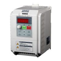
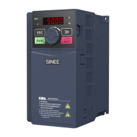
Details the physical components of the EM500 inverter, with illustrations for different models.
Guides users on how to check the inverter for damage or missing components upon receipt, as per a checklist.
Provides the overall dimensions and installation specifications for EM500 inverters and keypads across different models.
Outlines the necessary conditions for the installation site, including ventilation, temperature, and avoiding sunlight or corrosive gases.
Specifies the required vertical installation direction and clearance space around the inverter for proper cooling.
Provides step-by-step instructions on how to remove and install the keypad on the EM500 inverter.
Explains the procedure for converting the EM500 inverter for flush mounting type installation.
Shows the standard connection diagram for the EM500 inverter with its peripherals.
Details the main circuit terminals of the EM500, including input, output, DC bus, and grounding terminals.
Describes the control circuit terminals, including analog inputs, numeric inputs/outputs, and communication interfaces.
Explains how to connect an external keypad using an RJ45 interface and network cable.
Lists the checks to perform after wiring to ensure correctness and prevent issues.
Introduces the functions of the EM500's control panel, including LED keypads and their components.
Explains the four menu levels and three parameter display modes of the LED keypad.
Describes how to check for fault types, output frequency, current, voltage, control mode, and working time when the inverter is in a fault state.
Outlines the two kinds of monitoring available: monitoring mode 0 and monitoring mode 1.
Explains how to upload and download parameters between the keypad and inverter for setting or copying parameters.
Describes the multiple action modes available after pressing the M.K key, with default being jog forward.
Details how to start and stop the inverter using the RUN and STOP/RESET buttons, and how F12.00 changes the stop mode.
Provides a step-by-step guide for performing the trial operation of the EM500 inverter.
Highlights important considerations and checks to perform before and during trial operation.
Explains the general structure of function codes and how parameters are described.
Presents a comprehensive table detailing all function codes, their descriptions, units, defaults, and types.
Covers basic parameters like drive control mode, command source options, and terminal control modes.
Details parameters for configuring the first motor, including type, rated power, voltage, current, and frequency.
Explains the functions and configurations of numeric and analog input terminals.
Describes the functions and configurations of multi-function output terminals (Y1, Y2) and relay outputs (R1, R2).
Covers parameters related to starting and stopping the inverter, including start mode and DC brake settings.
Details parameters for the V/F control mode, including V/F curve settings and voltage/frequency separation modes.
Explains parameters for vector control, such as speed proportional and integral gains, and torque control settings.
Lists various protection parameters like motor overload, overheating, and bus voltage control options.
Describes parameters for setting multiple preset speeds and configuring the Simple PLC function.
Explains parameters for PID control, including setting sources, gains, and integral separation.
Details parameters for Modbus and CANSinee communication, including addresses, bit rates, and protocols.
Describes how to select and set user-defined function codes for custom applications.
Explains parameters related to keypad functions, display modes, and parameter locking.
Covers parameters for torque control, including speed/torque control mode and preset torque settings.
Details parameters for configuring a second motor, mirroring the settings for Motor 1.
Explains auxiliary functions like JOG operation, acceleration/deceleration times, and frequency hopping.
Describes user-defined functions for specific applications like winding, air compressor, and water supply.
Explains the functions of virtual input and output terminals.
Details the process and importance of autotuning motor parameters for vector control.
Lists essential precautions to take before performing motor parameter autotuning.
Provides a step-by-step guide for performing stationary and rotational autotuning for induction and synchronous motors.
Lists common faults of the EM500 inverter, their causes, and troubleshooting steps.
Explains how to interpret warning codes displayed on the LED and the corresponding actions.
Provides guidance on analyzing faults and taking corrective actions based on trip codes.
Outlines regular maintenance tasks, checks during normal running, and replacement terms for components.
Details the warranty service conditions and charges for faults or damages.
Explains the necessity and selection criteria for braking resistors, including power and resistance calculations.
Lists the models of BR100 braking units available for EM500 inverters over 18.5 kW.
Provides recommendations for selecting appropriate cables for braking units and resistors due to high voltage and temperature.
Lists the available I/O Expansion Cards and Communication Expansion Cards for EM500.
Describes the installation base specifications and installation method for EM500 inverters.
Explains the use of upper mounting holes for large-power EM500 inverters to stand against walls.
Details the installation of copper rows for cable switchover, including wiring and bolt specifications.
Defines the applicable series (EM500) and network (MODBUS-RTU) for the communication protocol.
Describes the RS-485 physical interface, including network address, data format, and bit rate.
Explains the structure of a standard MODBUS RTU message, including frame format and content definitions.
Details time intervals for interframe and intraframe communication and data frame processing.
Provides examples of Modbus communication requests and responses for common operations.
Defines the applicable series (EM500) and network (CANopen) for the communication protocol.
Describes the CAN bus topology, baud rate, and transmission distance.
Explains the standard CAN frame format, including header, identifier, DLC, data segment, and CRC.
Explains the application of broadcast messages for multi-machine synchronization.
Describes normal and abnormal response messages, including function code and data field differences.
Provides examples of Modbus communication requests and responses, including abnormal cases.
Describes the general specifications and resources of the EC-IO-A1 card.
Provides instructions for installing the EC-IO-A1 card into the expansion slot EC-B.
Details the terminal functions for the IO Expansion Card, including input, output, and power supply.
Describes the general specifications and resources of the EC-IO-A3 card.
Provides instructions for installing the EC-IO-A3 card into the expansion slot EC-B.
Details the terminal functions for the IO Expansion Card 3, including switch settings.
Describes the EC-CM-P1 card as a PROFIBUS-DP slave communication card.
Provides instructions for installing the Profibus-DP expansion card into the EC-B slot.
Details the terminal functions for the Profibus-DP Expansion Card.
Describes the EC-CM-C1 card as a CANOPEN slave communication card.
Provides instructions for installing the CANopen expansion card into the EC-B slot.
Details the terminal functions for the CANopen Expansion Card.
Describes the EC-CM-D1 card as a DeviceNet slave communication card.
Provides instructions for installing the DeviceNet card into the EC-A expansion slot.
Details the terminal functions for the DeviceNet Expansion Card.
Describes the EC-IO-K2 card for EM500 series inverter control terminal expansion.
Provides instructions for installing the IO expansion card into the EC-A expansion slot.
Details the terminal functions for the IO Expansion Card.
Describes the EC-TM-A1 card for EM500 series inverter control terminal expansion.
Provides instructions for installing the IO expansion card into the EC-A expansion slot.
Details the terminal functions for the IO Expansion Card.
Describes the EC-PSPP-A1 card for EM500 series inverter control terminal expansion.
Provides instructions for installing the IO expansion card into the EC-A expansion slot.
Details the terminal functions for the IO Expansion Card.
| Output Power | 500W |
|---|---|
| Frequency | 50Hz / 60Hz |
| Input Voltage | 12V DC / 24V DC / 48V DC |
| Output Voltage | 220V AC |
| Protection Features | Overload, Over Voltage, Over Temperature, Short Circuit |
| Cooling | Fan |


 Loading...