EM500 Open-Loop Vector Control Inverter User Manual
41
3.2.5Wiring on Input Side of Main Circuit
3.2.5.1Circuit Breaker Installation
An air circuit breaker (MCCB) corresponding to inverter is required between power
supply and input terminals.
The capacity of MCCB shall be 1.5 to 2 times that of the rated current of
inverter.
The time characteristics of MCCB must meet the time characteristics of
the overheating protection of inverter (150% rated current/1 minute).
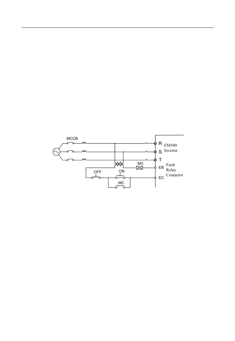
When MCCB is used with multiple inverters or other devices, please
connect the contactor of the fault output relay to power contactor coil, so that
the power supply will be turned off by a fault signal (Figure 3-5).
Figure 3-5 Connecting to Input Circuit Breaker
3.2.5.2Leakage Circuit Breaker Installation
Inverter outputs high-frequency PWM signal, which generates high-frequency
leakage current. Please select a leakage circuit breaker with trigger current ≥ 30mA. For a
regular circuit breaker, the trigger current ≥ 200mA and the active time at 0.1 s or above.
3.2.5.3Electromagnetic Contactor Installation
Connect the electromagnetic contactor corresponding to inverter power as shown in
Figure 3-4.
Do not control the start or stop of inverter with the electromagnetic
contactor on the input side. Frequent use of this method is an important cause
of damaging inverter. The operation interval between start and stop of inverter