EM500 Open-Loop Vector Control Inverter User Manual
39
Table 3-1 90 kW – 400 kW Terminal Dimension
Note: 90 kW or above: Power input terminals are on the top and power output terminals
are at the bottom of inverter. 220 - 400 kW or above: There are 2 wiring terminal blocks
for each phase.
3.2.2Main Circuit Terminal Functions
The main circuit terminal functions of EM500 are shown in Table 3–2 and please
correctly wire terminals according to functions.
Table 3–2 Main Circuit Terminal Functions
AC power supply input terminal, to connect to 3-phase AC power supply.
AC output terminals of inverter, to connect to 3-phase AC motor.
Positive and negative terminals of internal DC bus, to be connected to the external braking
unit.
Braking resistor connection terminals, one end connected to and the other end to PB.
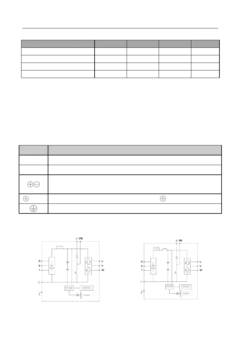
3.2.3Internal Main Circuit
The internal main circuit structure of EM500 is shown in Figure 3–3.