EM500 Open-Loop Vector Control Inverter User Manual
459
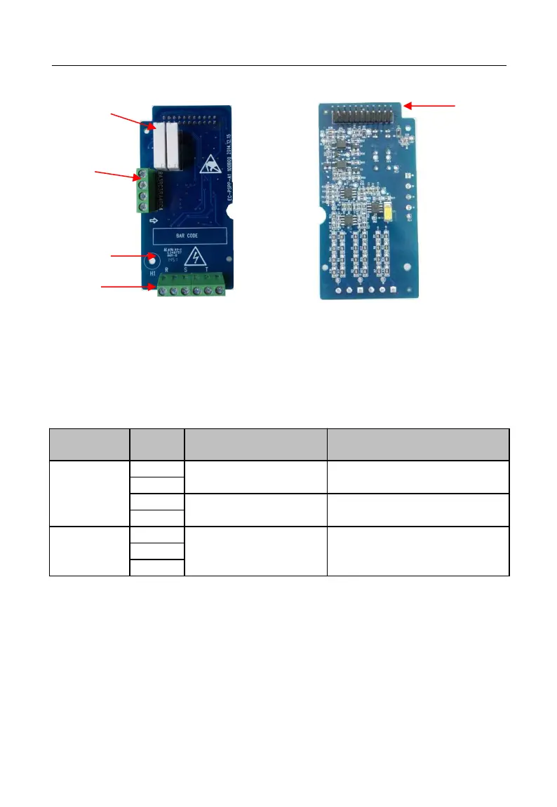
Figures of real objects are as follows:
Elevation Back Elevation
1. Output relay 2. Relay output terminal 3. Analog signal interface
4. Screw positioning hole 5. Inverter interface
Ⅷ.3 Expansion Terminal Function
Table 14 IO Expansion Card Terminal Function
Terminal function description
R3 power frequency
switching relay
Used to control the power grid to
the motor's contactor
R4 inverter startup is
completed relay .
Used to control the inverter to the
motor contactor
Used to detect the phase sequence
phase angle of the grid