EM500 Open-Loop Vector Control Inverter User Manual
384
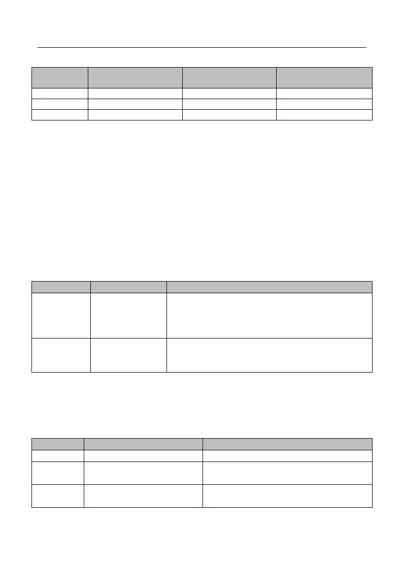
Table 11-1 Cable for Braking Unit and Braking Resistor
Average braking current
I
av
(A)
Section of copper core
cable (mm
2
)
Flexible cable has better flexibility. Since cable may contact high-temperature
device during use, it’s better to use copper core or heat-proof flexible cable or
fire-retardant cable. Braking unit and inverter should be as close as possible to each other,
and it’s better to keep their distance no more than 2 m, otherwise DC side cable should be
twisted and sheathed with magnetic ring to reduce radiation and inductance.
The length of the cable between inverter and braking unit should be less than 2m.
The length of the cable between braking unit and braking resistor can be more than 2m.
11.4.1 I/O Expansion Card Configuration
I/O expansion card is used for the expansion of inverter control terminal. Specific
model of I/O card is listed in Table 11-2.
Table 11-2 Model List of I/O Card
4 numeric multi-function digital signal inputs: X8 -
X11
1 numeric signal output: Y3
1 analog signal input: AI4
1 relay output (NO): Y3
1 temperature input: T1/T2
1 power supply: +15Vdc
11.4.2Communication Card Configuration
EM500 inverter is equipped with multiple communication expansion cards. Models
of expansion cards are listed in Table 11-3.
Table 11-3 Models of Communication Expansion Cards
CANopen Communication Card
125 kbps, 250 kbps, 500 kbps and 1 Mbps
DeviceNet Communication
Card
125 kbps, 250 kbps and 500 kbps
Profibus-DP Communication
Card