EM500 Open-Loop Vector Control Inverter User Manual
19
limit (upper limit frequency limit, maximum frequency limit, direction limit and
frequency hopping limit). The setting descriptions are given in Figure 1-2 to Figure 1-4.
主频率切换
DI:51~56
0:数字频率给定F00.07
1:AI1*F00.16
2:AI2*F00.16
3:AI3*F00.16
4:AI4*F00.16
5:HDI*F00.16
0
1
2
3
4
5
主
频率源
增益
F00.10
多段速端子
DI:14~11
0
n=1,2,…,15
第n段速
F08.00~F08.14
无
有效
F00.07
AI1
AI2
AI3
HDI(脉冲)
通讯
+
+
6:SCI*F00.16
6
UP/DOWN给定
+
+
Preset speed terminal
DI: 14 - 11
Main frequency
switching
DI: 51 – 56
Disabled
Enabled
Preset speed n
F08.00 – F08.14
Main frequency
source A
F00.04
HDI (pulse)
Communication
0: Numeric frequency setting
F00.07
1: AI1 * F00.16
2: AI2 * F00.16
3: AI3 * F00.16
4: AI4 * F00.16
5: HDI * F00.16
6: SCI * F00.16
UP/DOWN setting
Main
frequency
source gain
F00.10
Figure 1-2 Main Frequency Source A Setting
As indicated in Figure 1-2, when setting main frequency source A, user needs to
consider settings and status of numeric terminals comprehensively. According to terminal
settings, inverter can run at a preset speed or at a speed determined through numeric
setting, analog input, pulse or communication.
If all the numeric terminals are disabled, function code F00.04 is used to set present
channel and is in arithmetic together with UP/DOWN to get the final setting.
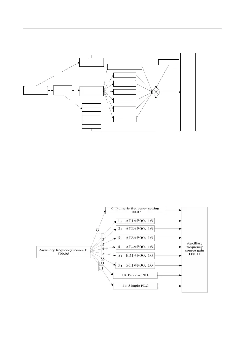
Figure 1-3 Auxiliary Frequency Source B Setting